


Pressure Control Board
20 311365G
Pressure Control Board
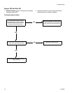
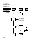
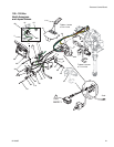
100 - 120 Vac North American and Japan/Taiwan Motor Control Board
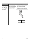
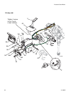
Removal
Relieve pressure; page 9. Wait 5 minutes before
servicing.
1. Remove four screws (38) and cover (96).
2. Disconnect display connector (A) from motor
control board.
3. Remove bottom two screws (39) and allow
control panel (68) to hang down freely.
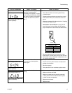
4. Disconnect control board power lead(s) (D)
from ON/OFF switch (33) and motor control
board (52).
5. Disconnect potentiometer connector (C) from
motor control board.
6. Disconnect WatchDog (49) switch connector
(X) from motor control board.
7. Disconnect 15/20A switch (178) (1595 model
only).
8. Disconnect transducer connector (E) from
motor control board.
9. Disconnect motor connectors (F, G, and H)
from motor control board.
10. Remove motor shroud. Disconnect and remove
wiring from baffle.
11. Remove nut and screw (88) and disconnect
ground wire (87). Disconnect coil connector
(Y). Remove coil (81).
12. Remove top two screws (39) and control box
(61).
13. Remove six screws (27), two screws (102) and
control board.
14. Remove five screws (27), three screws (102)
and motor control board.
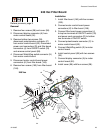
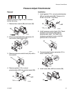
Installation
1. Apply small amount of thermal compound
15U114 or 110009 (5) to shaded component
areas on rear of motor control board (52).
2. Install five screws (27), three screws (102) and
motor control board.
3. Install motor control board (52) with five screws
(27). Torque to 9-11 in-lb (1.02 - 1.24 N•m).
Install and torque three screws (102) to values
in illustration.
4. Connect motor connectors, (F, G and H) to
motor control board.
5. Reconnect and install wiring in baffle. Install
motor shroud.
6. Install control box (61) with top two screws (39).
7. Install coil (81) and tighten screw and nut (88).
Tighten ground wire screw (87) and coil
connector (Y).
8. Connect transducer connector (E) to motor
control board.
9. Connect 15/20A switch (178) (1595 model
only).
10. Connect motor control board power lead(s) (D)
to ON/OFF switch (33).
11. Connect WatchDog (49) switch connector (X)
to motor control board.
12. Connect potentiometer connector (C) to motor
control board.
13. Install control panel (68) with two screws (39).
14. Connect display connector (A) to motor control
board.
15. Install cover (96) with four screws (38).
CAUTION
To reduce risk of motor control board failure, do
not overtighten screws (102) which can damage
the electric components.