


6
Digital Temperature Interlock
®
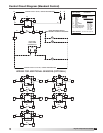
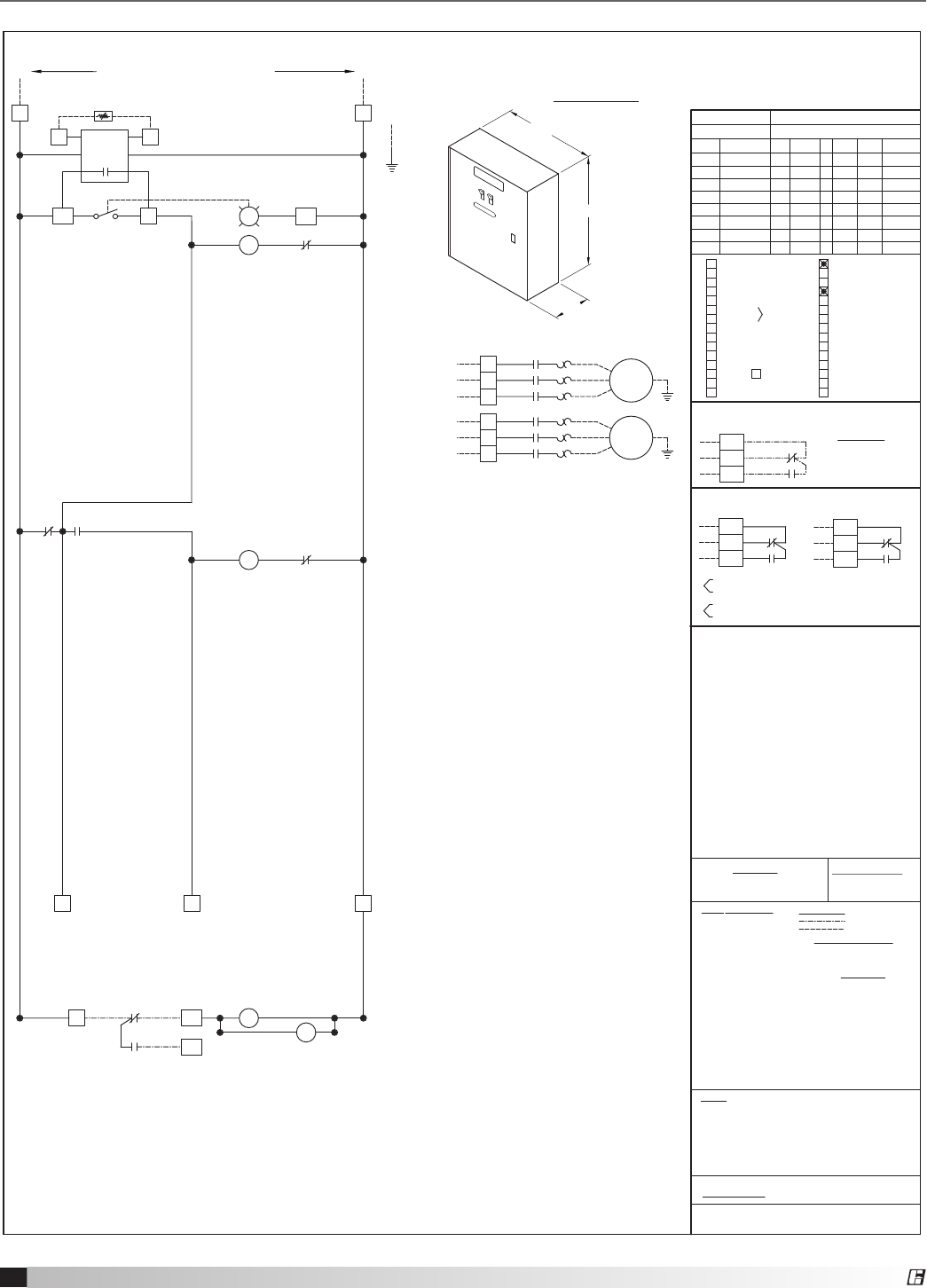
Control Circuit Diagram (Fan Control Center)
closed w/power at H1/N1 & re sys. armed
open w/power at H1/N1 & re sys. armed
(can be used for shunt trip, alarms, etc.)
Spare Relay Contacts
closed on re or no power
open on re or no power
4
3
A
B
B
A
NC3
BK
C3
NO3
RD
BR
NO4
NC4
A
B
R2
1
C4
5
BK
8
6
RD
BR
R2
(activated by FS1)
R2
2 7
RD
1
4
R1
96
A1
YW
A2
ST
WH
OL
95
2
2
96
A1
OR
A2
ST
WH
OL
95
1
1
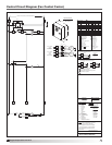
3 WIRE
FROM BREAKER
3 PHASE
INPUT POWER
L2
L3
L3
L1
L2
L1
ST
T3T3
FAN
T1
T2
T1
T2
OL
G
1
1
1
EXH
3 WIRE
FROM BREAKER
3 PHASE
INPUT POWER
L2
L3
L3
L1
L2
L1
ST
T3T3
FAN
T1
T2
T1
T2
OL
G
2
2
2
SUP
FAN
LIGHTS
Fan Switch
Lights Switch
RD
S1
OR
R
LT1
WH
S1H S1
S1N
KFCC
HD-1
F1 EF-1
1.5
460
3 3.0
14ga
15amp
F2
MAU-1
1.0
460
3 2.8
14ga
15amp
18 inches
6 inches
12 inches
CONTROL PANEL
C
NO
BK(YW)
RD
RD(RD)
C1
D3
NC
FS1
BR(BK)
NO1
NC1
BR
2
R1
D1
7
WH
D2
CONTROL INPUT: 120VAC, 15AMPS FROM BREAKER
R1
1
OR
3
H1
L1
N1
N
G
T1
NOC
T1 T2
TC1
WH
OR
OR
RD
YW YW
Volt
Spare Fire Switch Contact
(dry contacts for building alarm)
Gas O w/Fans
Qty. Temp. Switches (0-1)
Remote Switches
Tempering SW
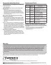
TERMINAL STRIPS = 18 IN/LB.
GROUNDING BAR = 20 IN/LB.
UNDER SUBJECT 891
STB Shunt Trip Breaker
If wall mounted prewire, or eld installed re
system, the re system microswitches must
(in normal operation, R1 & R2 are energized)
with re system armed (non-re mode).
Drawing shown de-energized at L1 (term.#H1),
KFCC-TEMP-INTERLOCK
AF Air Flow Switch
be eld wired.
UL LISTED
Wiring Diagram #
D Damper
EC Evap Cooler
TC Temperature Controller
PB Push Button
SV Gas Solenoid
NOTES:
ST Starter
S Switch
LT Light
G Ground
FS Fire Switch
EF Exhaust Fan
SF Supply Fan
OL OverLoad
C Contactor
R Relay
LABEL DESCRIPTION
TORQUE:
RD(RD)
C2
NO2
NC2
BK(YW)
BR(BK)
C
NC
NO
X
Audible ALarm
Gas Reset
Evap Cooler Switch
Power for Gas Solenoid
Power for Shunt Trip
Pushbutton Switches
B
V
P
R
G
A
Q
Heat Switch
Cool Switch
AD Switch
One Switch for L & F
One Breaker Con. L & F
Qty. Light Switches (0-3)
Qty. Fan Switches (0-3)
0
1
H
I
Y
C
#
#
#
1
1
Hood Mark(s):
Fan MarkMotor HP
Panel Mark:
OR - orange
FILE #E200616
YW - yellow
WT - white
RD - red
PR - purple
FIELD WIRING
HOOD WIRING
BK - black
BL - blue
WIRE COLOR
UNLESS SPECIFIED
ALL WIRING 90°C 14 GA.
BR - brown
use minimum
60° Copper Wire
FIELD WIRING:
FACTORY WIRING
Ansul(Amerex)
RD(RD)
BK(YW)
BR(BK)
FS2
O
EF Failure Light
O Delay Relay
SF Failure Light
Aux. Supply Contact
Fan Failure Light (Appl.)
Tie in WWCP
W
Damper
K
J
D
U
N
Exhaust in Fire
Lights Out in Fire
DPDT Relay w/SF
DPDT Relay w/EF
Fire Relay (#1)
Extra Fire Relay (#3)
Extra Fire Relay (#2)
MUA Interface
-9
T
F
E
S
2
L
M
WirePH
FLA
Breaker
YW
10
4
2
12
5
1