


705 South Electric Ave. Alhambra CA, 91803
626.289.7618 Fax: 626.289-8121 info@grexairbrush.com
© 2005 Grex Power Tools. All Rights Reserved.
All Grex spray guns are warranted against manufacturing defects of material and manufacture or workmanship
for a period of ONE year from the original date of purchase. This warranty does not cover fluid needles, fluid
nozzles and o-rings since these parts need to be replaced occasionally due to normal wear. Any parts of the
product covered under this warranty will be repaired or replaced at our option, which after examination proves to
be defective in workmanship or material during the warranty period.
This warranty does not apply to repair or replacement parts required due to misuse, abuse, normal wear and tear
or repairs and alterations attempted. In no event shall Grex be liable for any indirect, incidental, or consequential
damage from the sales or use of this product. This disclaimer applies both during and after the term of this
warranty.
This is the only warranty and our company makes no warranties express or implied, including merchantability
and fitness for a practical purpose, after the one year term of this warranty.
This limited warranty gives you specific rights and you may also have other rights, which vary from state to state.
WARRANTY
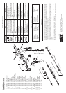
No.
1
1-1
1-2
1-3
2
3
3-1
4
5
6
6-1
6-2
6-3
6-4
6-5
7
8
9
10
11
12
12-1
12-2
12-3
13
14
15
15-1
15-2
16
17
17-1
17-2
17-3
17-4
17-5
18
19
20
Part No.
X1000NCS
A150027
A041000
A120006
A051000
A021000
A150028
A120008
A150029
X1000ACA
A150030
A150031
A150032
A120009
A150033
A011000
A110006
A150034
A150035
A120007
A150036
A120010
A150037
A060008
A150038
A110007
A150039
A120011
A150040
A150041
X1000AVA
A150042
A150043
A150044
A120012
A150045
A150046
A150047
A150048
Part Description
Air Nozzle Cap Set
Brass Ring
Air Nozzle
Teflon Ring
Fluid Nozzle
Fluid Needle
Fluid Needle Seat
Needle Packing
Needle Packing Seat
Fan Air Control Assembly
Air Piston
E-Ring
Air Control Seat
Teflon O-Ring
Air Control Knob
Spray Gun Body
Fluid Needle Spring
Fluid Adjust Knob
Air Valve Stem
Teflon O-Ring
Air Valve Seat Set
Gasket
Seat Nut
O-Ring
Air Valve
Air Valve Spring
Fluid Adjust Guide Set
Teflon O-Ring
Guide Nut
Air Nipple
Air Regulator
Air Piston
E-Ring
Air Control Seat
Teflon O-Ring
Air Control Knob
Trigger Stud
Trigger
E-Ring
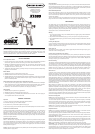
TROUBLESHOOTING GUIDE
Air enters between fluid nozzle and seat
of gun body.
Air is suctioned from fluid needle packing.
Paint buildup on air cap partially clogs
horn holes. Air pressure from both horns
differs.
Paint buildup on air cap partially clogs
horn hole or air cap center hole, or causes
damage
Loose fluid nozzle
Paint viscosity too low
Fluid output too high
Paint viscosity too high
Fluid output too low
Fluid nozzle and fluid needle set are not
seated properly.
The first stage travel of trigger (when only
air discharges) decreases.
Paint buildup inside air cap set.
1.
2.
1.
1.
2.
1.
2.
1.
2.
1.
2.
3.
Remove fluid nozzle to clean seat
Tighten fluid needle packing.
Remove obstructions from horn holes, but
do not use metal objects to clean horn
holes.
Remove obstructions.
Replace if damaged
Remove nozzle and clean seated section
Add paint to increase viscosity
Adjust fluid or pattern adjustment knob
Reduce viscosity
Increase fluid output
Clean or replace fluid nozzle and fluid
needle set.
Replace fluid nozzle and fluid needle set.
Clean air cap set.
1.
2.
1.
1.
2.
1.
2.
1.
2.
1.
2.
3.
Problem RemediesSpray Pattern
Spit
Heavy Center
Split
Inclining
Crescent
Fluttering
Air Consumption
Fluid Output
Air Inlet
Fluid Inlet
Working Pressure
7 cfm (200 L/min)
115 mL/min
1/4” NPS
1/4” NPS
30 ~ 45 psi
TECHNICAL SPECIFICATIONS
Fluid Nozzle
Feed Type
Fluid Capacity
Container Type
Pattern Width
Weight
1.0 mm
Side Gravity
8.5 oz. (250 ml)
Side detachable cup
11” (280 mm)
1.3 lbs. (0.58 kgs)
6-5
6-2
6-1
6-4
6-3
6
1-1
1-2
1-3
2
16
1
4
16
17-1
17-2
17-3
17-4
17-5
17
20
19
18
5
7
3-1
15-2
15-1
15
3
8
9
10
11
12
12-1
12-2
12-3
13
14