G1182 6" Series Jointers -15-
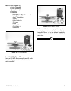
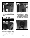
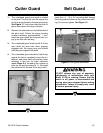
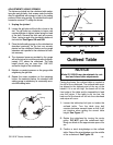
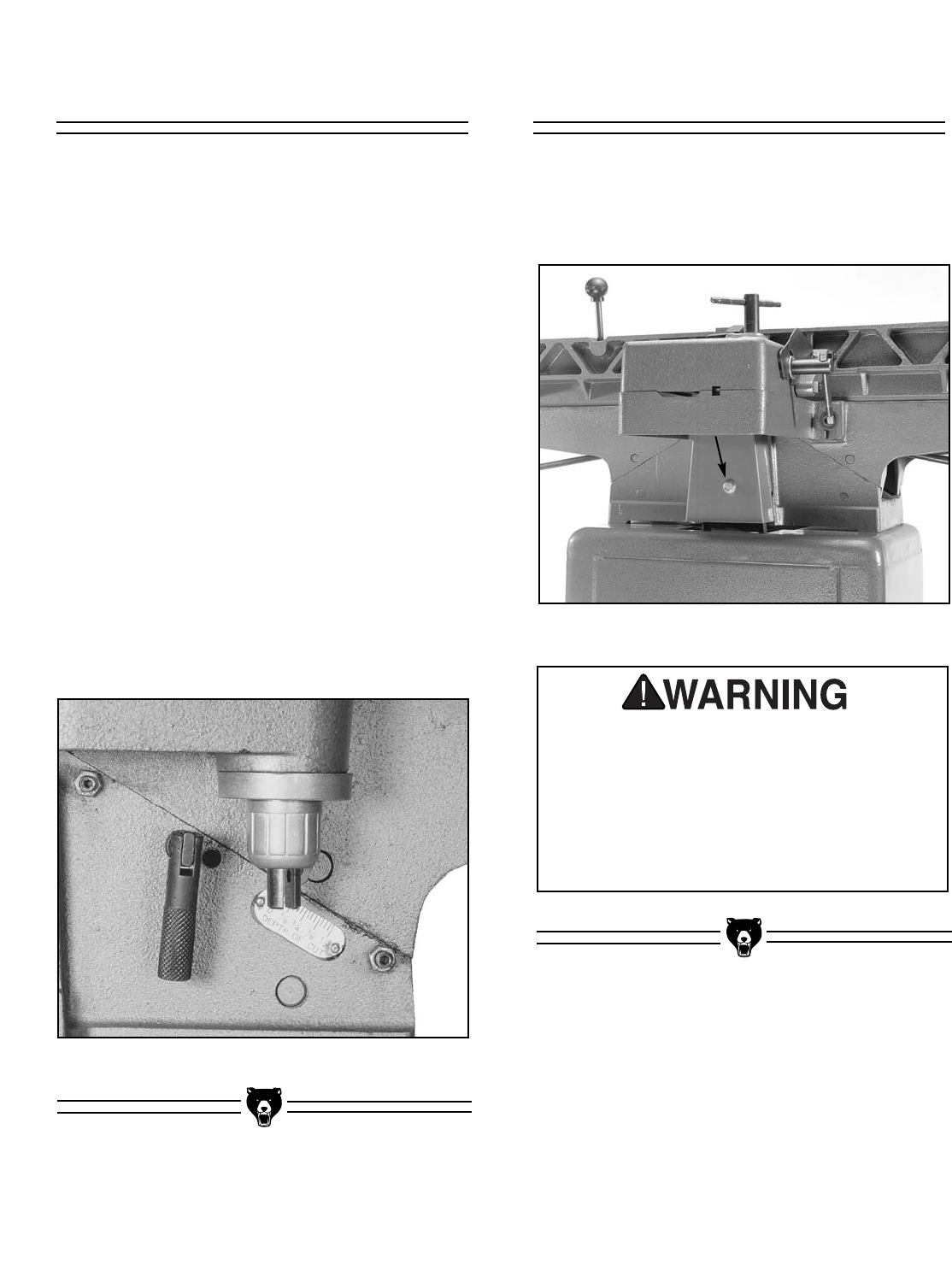
1. The cutterhead guard pivot shaft is slotted
on the end. This slot fits over the tang at the
end of a spring located in the spring housing.
See Figure 11. Look down the pivot hole to
get an idea where this tang is located.
2. Remove the setscrew from the slotted end of
the pivot shaft. Rotate the spring housing
counter-clockwise approximately 1 turn.
Insert the guard shaft into the pivot hole, lin-
ing up the slot with the tang.
3. The cutterhead guard shaft should fit all the
way inside the pivot hole when properly
engaged with the spring tang and should
hold the guard against the fence.
4. The cutterhead guard should be held firmly
against the fence, completely cover the cut-
terhead, and move back into position when
released. If this has not been achieved,
repeat Steps 2-3, increasing the number of
turns on the spring housing to 1
1
⁄2. Re-install
the setscrew into the end of the pivot shaft.
Figure 11. Spring housing.
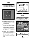
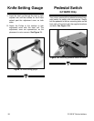
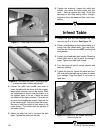
Insert the
5
⁄16" - 18 x 2
1
⁄2" mounting bolt through
the belt guard and attach to the jointer base cast-
ing. Do not over tighten. See Figure 12.
Figure 12. Belt guard attachment.
DO NOT attempt any step of assembly,
adjustments, or maintenance while your
Model G1182 is running. Ensure that the
switch is off, power is disconnected and
moving parts have stopped before making
adjustments. Failure to comply may result
in serious personal injury.
Cutter Guard Belt Guard


