


G5049Z Combination Sander -9-
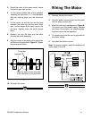
Figure 5.
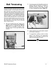
Align the center of the drive disc
to the centerline of the jack shaft
C/L
Jackshaft
Drive disc
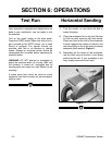
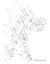
Figure 6.
10. Re-install the cover.
5. Mount the motor to the motor mount. Leave
the bolts finger tight for now.
6. Lift the spring loaded side of the jackshaft
assembly up and insert a
1
⁄16'' shim between
the cast bearing block and the aluminum
pad.
7. Lift the motor up and slip the two flat bars
between the stand top and the motor drive
disc. Let the weight of the motor rest on the
flat bars. Tighten down the motor mount
bolts.
8. Remove the two flat bars and the shim
fromthe jack shaft assembly.
9. Align the center of the motor drive disc to the
centerline of the jack shaft. Figure 5. Tighten
the motor mount bolts.
Wiring The Motor
1. Remove the wire box cover.
2. Feed the power source wires from the switch
into the motor junction box.
3. Wire the motor per the diagram in Figure 6.
The wires from the power supply, besides
the Green Ground wire, are interchangable,
therefore colors are not specified.
4. The green wire from the cord is grounded to
the motor casing.
5. Re-install the wire box cover.
Note: To reverse rotation, switch the positions of
motor wires #5 and #6.