


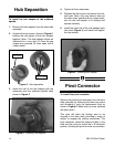
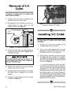

Figure 11. Completed collet closer assembly.
G8143 Collet Closer-6-
2. Please note that the rod connector is sup-
plied with jam nuts. It may be necessary to
remove these nuts to allow for the proper fit
of the assembly on some lathes.
3. Install the handle to the yoke. Note—If you
have trouble positioning the locking yoke so
it is aligned with the draw tube in the next two
steps, adjust the length of the connecting rod
by threading it more or less into the pivot
connectors and try again.
4. Make sure the locking yoke and the rod con-
nector are secured to the mounting stud and
the pivoting rod connecter.
5. Position the locking yoke back inline with the
setscrew holes on the draw tube assembly,
then secure the setscrews and the jam nuts
as shown in Figure 10.
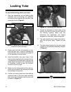
Figure 9. Connecting rod and locking yoke
installed on pivot connector.
Locking Yoke
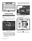
Figure 10. Tightening yoke setscrews.
6. Thread the setscrews on both sides of the
locking yoke into the holes on both sides of
the bearing housing. Make sure the
setscrews are completely and evenly
engaged into the holes, without being tight.
7. The yoke should have no play from side-to-
side, but still pivot freely. Tighten the jam
nuts.
8. The ideal locked position for the collet closer
is shown in the completed assembly diagram
in Figure 11.
Locking
Yoke
Connecting
Rod
Pivot Connector
To secure the locking yoke to your lathe:
1. Align the connecting rod and locking yoke
assembly onto the pivoting rod connector
and secure them together with the 8mm cap
screw as shown in Figure 9.