


G8297/G8298/G8299 Air Compressors
-9-
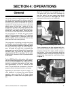
SECTION 4: OPERATIONS
The pump produces compressed air which goes
into the air tanks through the delivery pipe and
the check valve. When the air pressure arrives at
the factory pre-set level of 135 PSI, the pressure
switch shuts off the electrical current to the axial
electric pump. At the time it shuts off, it dis-
charges the air held in the pump cylinder to the
delivery pipe. This allows the pump to be depres-
surized so it can easily restart. When the pres-
sure in the air tanks falls below the minimum fac-
tory set pressure of 105 PSI, the pump cycles
again to build the pressure back up. The pressure
switch is supplied with a discharge valve with
delayed closing, which reduces the strain on the
pump and the motor during startup.
The compressor is operating correctly when there
is a bleed of air every time the motor is switched
off. You will notice an audible air discharge each
time the pump motor stops. On these compres-
sors, the pump will cycle first to minimize the
amperage draw and will bleed off air through the
cold-start valve. The valve will stay open until
approximately 20 PSI is reached in the air tanks
at which time it closes to allow full pressurization
of the tanks.
For the G8299 with the dual motors, both motors
can be started simultaneously for rapid pressur-
ization. As with the G8298, the 2.5 HP pump is fit-
ted with a cold-start valve which will stay open
until approximately 20 PSI is reached in the
tanks. This will allow the compressor to lubricate
properly without straining the motor and pump.
Depending on the volume of the air usage, it is
often adequate to recharge the system during
operation using only the 2 HP pump taking
advantage of its lower RPM and quieter opera-
tion.
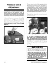
General
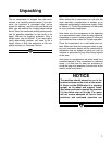
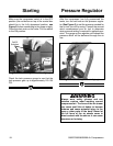
Fig 3. Pressure safety relief valve.
All of the compressors are equipped with a 150
PSI safety relief valve which will discharge air
from the tanks if for any reason they should
become over-pressured. See Figure 3. These
are preset valves and are not adjustable.
Relief Valve
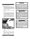
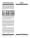
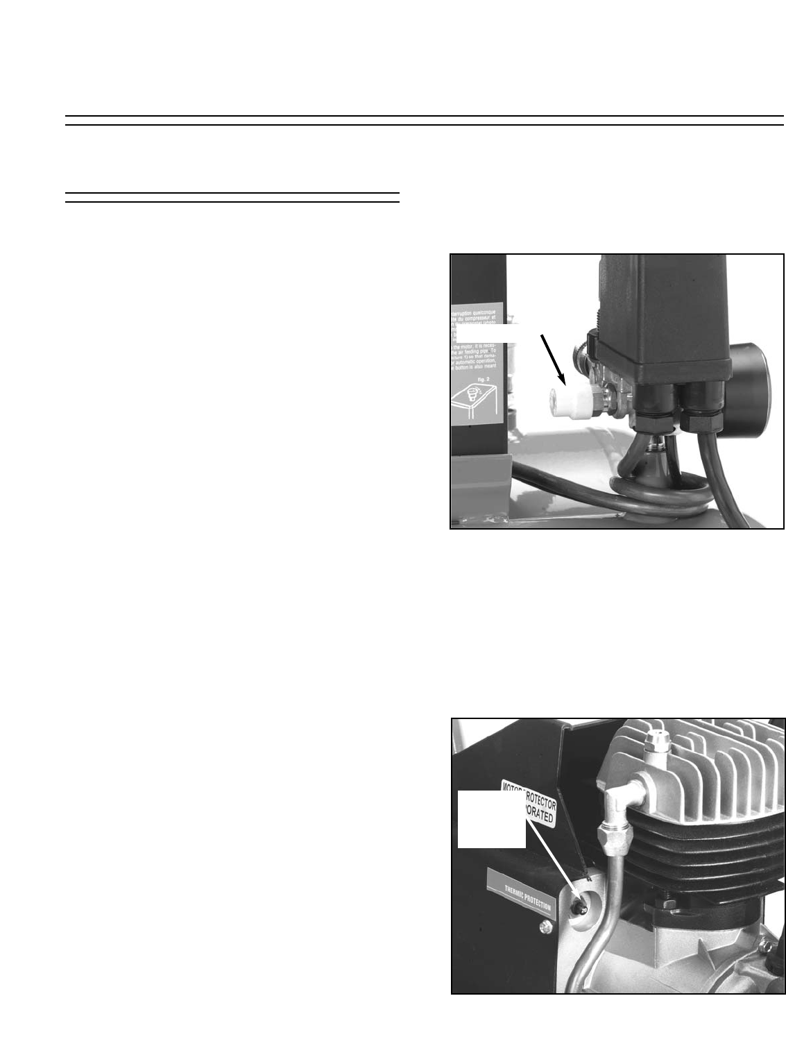
Fig 4. Thermal protection typical placement.
Thermal
Overload
Switch
These compressors are also equipped with ther-
mal overload breakers which will trip if there is
excessive load on the motors which causes a
heat buildup. In the event the breaker shuts the
compressor down, wait a few minutes for the unit
to cool down, then press the reset button shown
in Figure 4.