


-9-
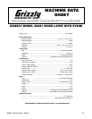
G8691 Wood Lathe w/ Stand
SECTION 4: ASSEMBLY
Beginning Assembly
Most of your Model G8691 Wood Lathe has been
assembled at the factory, but some parts must be
assembled or installed after delivery. We have
organized the assembly process into steps.
Please follow along in the order presented here.
TOOLS REQUIRED: A metric socket set, 6"
adjustable wrench, and Phillips
®
head screw dri-
ver.
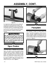
The stand consists of 8 pieces; 4 legs and 4 sta-
bilizer bars. With the included bolts, washers and
nuts, assemble the 4 stabilizer bars to each of the
4 legs, being certain not to fully tighten the assem-
bly at this time.
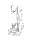
With the stand pieces together, use a bench or
stand to place the lathe unit upside down as
shown in Figure 2. Attach each of the 4 legs to
the base of the lathe unit, making sure that the
bolts are tight. Tighten the remaining bolts located
at each of the stabilizer ends. Turn the lathe and
stand right-side up and check to see if the lathe
bed is parallel to the ground. Loosen and adjust
the stand bolts accordingly until the lathe is level.
Be careful not to loosen the bolts too much as the
lathe may tip over. Make sure that all the bolts are
securely tightened before continuing.
Stand
Figure 3.
All die-cut metal parts have a sharp edge
(called “flashing”) on them after they are
formed. This is removed at the factory.
Sometimes, though, a bit of flashing might
escape inspection. Please examine the
edges of all die-cut metal parts before han-
dling them. Serious injury may occur.
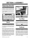
Tool Rest
The tool rest is equipped with a horizontal and a
vertical adjustment lever. By loosening the levers,
the tool rest can be precisely placed along the
workpiece for safe and efficient removal of wood
stock.
Tailstock
The Model G8691 is supplied with a #2 Morse
Taper live center. The tailstock can be adjusted
along the length of the lathe bed to accommodate
various lengths of wood stock. There are two
ways to adjust the tailstock. The bolt located
under the lathe bed can be loosened, allowing the
tailstock to slide up and down the length of the
lathe bed. The hand wheel can also be loosened
allowing the threaded spindle to move back and
forth in the tailstock. Figure 4.