


G8794 12
1
⁄2" Portable Planer
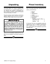
-11-
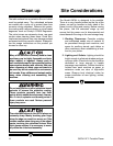
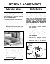
Figure 7. Aligning extension wings.
SECTION 6: ADJUSTMENTS
Extension Wings
Your planer is equipped with front and rear exten-
sion wings. Each wing folds up for machine
mobility and down for machine operation. To
check alignment, lay a straightedge across the
bed and wings. See Figure 7.
If adjustment is necessary, proceed as follows:
1. Use the 10mm wrench and loosen the lock-
ing nuts and set bolts underneath each
extension wing.
2. Hold a straightedge across the bed and
wing and turn the adjustment bolts so the
end of the wing is flush with the straight-
edge.
3. Move the straightedge across the width of
the table and repeat step two. Re-check to
ensure consistency from side to side.
Without turning the set bolts, tighten the
lock nuts.
4. To adjust the second wing, repeat steps
one through three above.
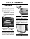
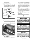
Adjustment Bolt and Locknut
Figure 8. Turn tightening bolt clockwise to loosen.
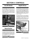
Knife Setting
The G8794 Planer is equipped with a 2 blade cut-
terhead. The blades are locked in position by a
knife locking bar with seven bolts angled to put
pressure on the assembly when they are tight-
ened. A set of two springs under each blade
pushes up to keep the blade portion exposed.
The knife setting gauge is used to push down on
the blade to set it to the proper height.
Disconnect the power cord from the power
source before adjusting or removing the
knives.
To remove the knives:
1. Lower cutterhead to provide access to
knives from the top.
2. Remove chip deflector.
3. Use the 8mm end of the wrench to loosen
the bolts in the knife locking bar. Turn
clockwise to loosen bolts and free the
knife! (See Figure 8)
4. Slide knife out of cutterhead. Use care
when handling knives - they are sharp!
5. Repeat steps three and four above to