


Ultimate Series Jointers -11-
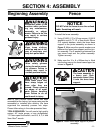
SECTION 4: ASSEMBLY
Beginning Assembly
Most of your Ultimate Series Jointer has been
assembled at the factory, but some parts must be
assembled or installed after delivery. We have
organized the assembly process into steps.
Please follow along in the order presented here.
TOOLS REQUIRED: You will need a high quality
square, 45° angle gauge, a long straightedge,
11/13mm open end wrench, and a 8, 6, 5, 4 and
3mm Allen
®
wrench.
Disconnect power to the
machine when perform-
ing any maintenance,
assembly or adjust-
ments. Failure to do this
may result in serious
personal injury.
!
Keep loose clothing
rolled up and out of the
way of machinery and
keep hair pulled back.
Wear safety glasses
during the entire assem-
bly process. Failure to
comply may result in
serious personal injury.
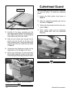
Fence
DO NOT slide the fence across the outfeed
table. Scratching will result.
NOTICE
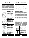
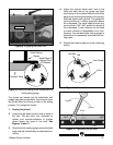
To install the fence assembly:
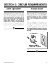
1. Using (2) M12-1.75 x 35 cap screws, (2) M12
washers, and (2)
5
⁄
8" I.D. x 3mm thick x 38mm
O.D. special washers, attach the fence base
support to the jointer assembly as shown in
Figure 3. Make sure the special washers are
between the fence base support and the join-
ter assembly. The 2 washers go between the
cap screw head and the jointer assembly.
Tighten securely.
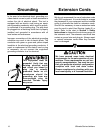
2. Make sure the 10 x 8 x 260mm key is fitted
into the key way on the fence base support as
shown in Figure 4.
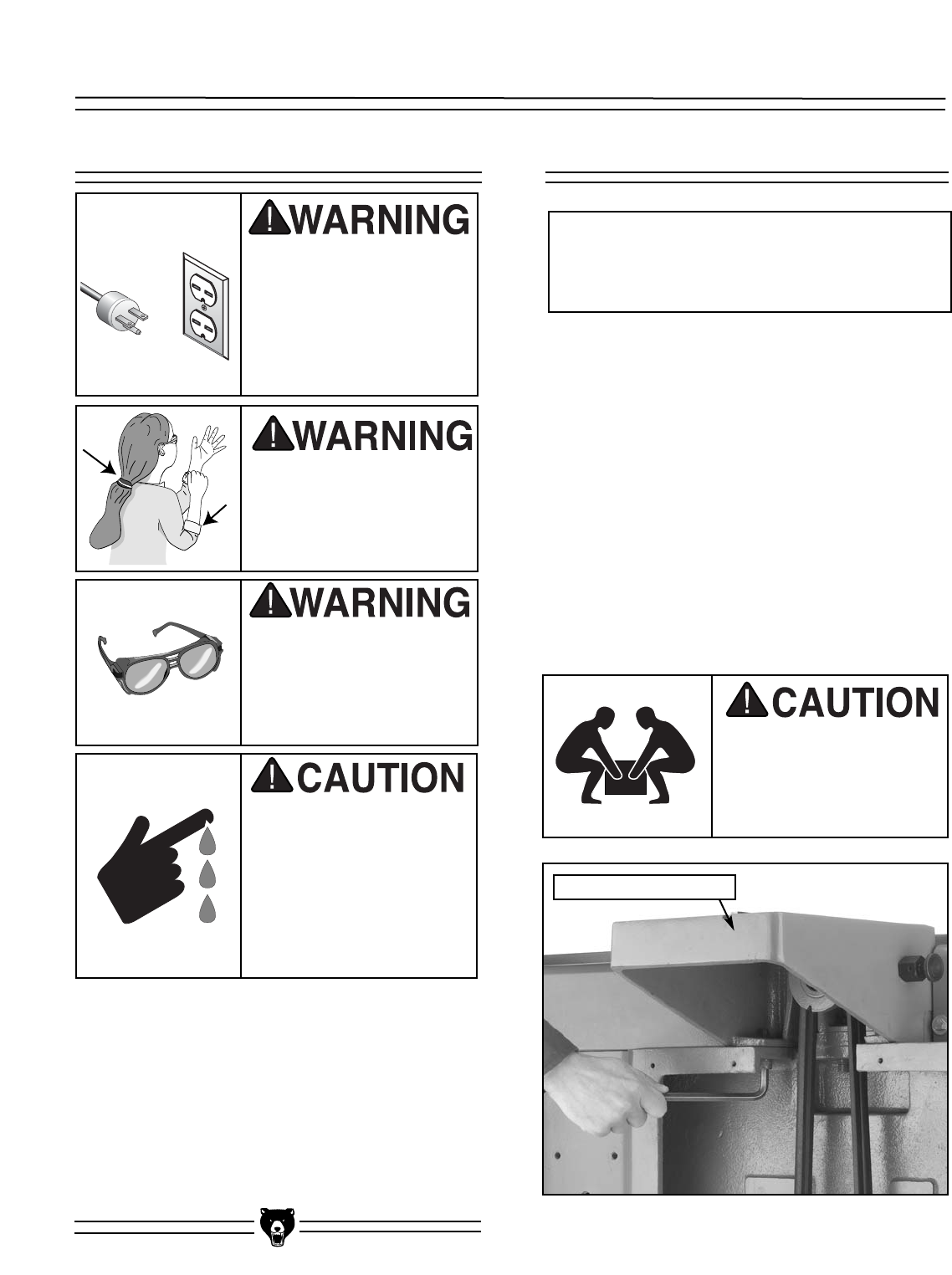
The fence assembly is
a heavy part. Seek
assistance when lifting
it onto the fence base
support.
Figure 3. Attach fence base support to jointer
assembly.
Some metal parts may
have sharp edges on
them after they are
formed. Please examine
the edges of all metal
parts before handling
them. Failure to do so
could result in injury.
Fence Base Support