


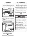

1. Use the hex bolts with a lock nut on one side
of the column clamp and a wing nut on the
other side to clamp the drill column as shown
in Figure 3.
ASSEMBLY
Figure 3. Column clamp.
1. Loosen the wing nut on the column clamp
and rotate the drill press support perpendicu
-
lar to the drill head. Tighten the wing nut.
2. Place a straightedge on the drill press table
and adjust the roller supports until they are
the same height as the drill press table.
3. Move the extensions in or out as necessary to
accommodate the length of the workpiece
.
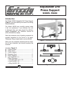
If you need additional help with these procedures,
call our service department at: (570) 546-9663.
ADJUSTMENTS
Failure to follow these instructions will
result in serious personal injury:
1. The addition of the Drill Press Support
increases the tipping hazard
. Bolt the drill
press to
a solid surface to prevent tipping.
2. Make sure the extension arms are inserted at
least 2" into the center support.
3. Use additional supports for extra long or
unusually heavy workpieces.
4. Push extension arms in when not in use to
reduce obstructions in your shop.
5. Center the workpiece to prevent tipping.
6. DO NOT exceed the weight capacity of the
drill press table.
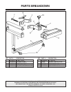
2. Slide the center support into the column
clamp and secure with a lock knob as shown
in Figure 3.
3. Insert the extensions into the central support
and secure with lock knobs (Figure 4
).
Figure 4. Support assembly.
4. Slide the roller supports into the extensions
and secure with lock knobs (Figure 4
).
Center Support
Column Clamp
Roller Support
Extension Arm