


-12-
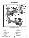
H8259 10" x 18" Benchtop Lathe
Assembly
Before use, the tool rest must be moved out of
its shipping position and the quill handwheel
knob must be attached.
Test Run
Once the assembly is complete, test run your
machine to make sure it runs properly and is
ready for regular operation.
The test run consists of verifying the following:
1) The motor powers up and runs correctly.
2) The safety paddle switch works correctly.
If, during the test run, you cannot easily locate
the source of an unusual noise or vibration, stop
using the machine immediately, then review the
Troubleshooting on Page 26. If you still cannot
remedy a problem, contact our Tech Support at
(570) 546-9663 for assistance.
To test run the machine:
1. Make sure that you have read the safety
instructions at the beginning of this manual
and that the machine is setup properly.
2. Connect the machine to the power source.
3. Turn the machine ON. Make sure that your
hand stays poised over the switch in case
you need to quickly turn the machine
OFF.
—When operating correctly, the machine
runs smoothly with little or no vibration or
rubbing noises.
— Investigate and correct strange or unusual
noises or vibrations before operating the
machine further. Always disconnect the
machine from power before investigating
or correcting potential problems.
4. Turn the machine OFF.
5. Remove the safety key and attempt to turn
the machine
ON.
—If the machine starts, stop it and disconnect
it from power. The switch disabling feature
is not working. This safety feature must
work properly before proceeding. Call Tech
Support for help.
—If the machine does not start, the switch
disabling feature is working.
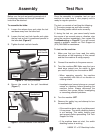
Figure 6. Tool rest positioned.
To assemble the lathe:
1. Loosen the release lever and rotate the tool
rest base away from the lathe bed.
2. Loosen the tool rest lock handle and rotate
the tool rest so that it is positioned parallel to
the lathe bed (
Figure 6).
3. Tighten the tool rest lock handle.
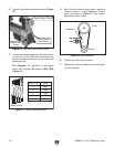
4. Secure the crank to the quill handwheel
(Figure 7).
Tool Rest
Lock Handle
Release
Lever
Figure 7. Quill handwheel crank installed.
Crank
Quill
Handwheel
Tool Rest
Base
Tool Rest