


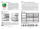
Control Panel Illustration
Mode
Power
On/Off
HEATING
KEEPING
SET
ACTUAL
1. Set Button
2. Temperature and Clock Time Increase Button
3. Temperature and Clock Time Decrease Button
4. Real-time Heating Indication
5. Medium Warm Indication
6. Night Power Indication
7. Heating Power Indication Area
8. Heating Indication
9. Delay Indication
10. Intelligent Indication
11. Mode Button
12. Power Level Selection Button
13. On/Off Button
14. Warm Keeping Indication
15. 2 Indication
16. Clock Time Display
17. Temp.Setting / Actual Temp Display
18. 1 Indication
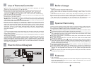
Time
Time
Signaling Indication
Real-time Heating Indication
Medium Warm Indication
Night Power Indication
Intelligent Indication
Delay Indication
Mode
Power
Confirm
Set
850 W
1300 W
2150 W
TIME 1
TIME 2
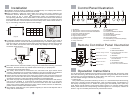
Remote Controller Panel Illustration
For the first use after installation, due to there's no water within the tank, first the city water
inlet valve and mixing valve must be opened. Close the mixing valve when water flows out
continuously from the showerhead or other outlets (the tank is full). Check connections
are free of water leakage, and insert the power plug.
1. Powering On
This product has a power failure memory function, i.e. it remembers temperature setting,
power level, clock and current working status. Upon connecting power, all indications on
the display are displayed for 2 s before the system goes into standby status (with only
clock display and all buttons except On/Off button inactive) or previous working status
before power failure with corresponding indicators lighted on. For example, machine as
shown in Fig. 6 is in standby status with only On/Off button active.
Operation Instructions
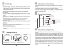
Installation
Installation must be made by installers of or designated by our company after-service
department. The water heatershall be wall-mounted.
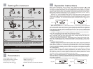
Before installation, make sure water heater rear wires are fit firmly. Determine an
installation location. Make four holes 12mm, 65 mm deep in the wall with an impact
drill as shown in Fig. 2. Insert and fixexpansion hooks and expansion bolts in
corresponding wall holes. Lift the water heater. Insert wall rack onto the hooks and bolts.
Fit flat washers, rear wires and nuts in turn onto the bolts (see Fig. 3). Tighten the nuts
and check them firm. Install accessories such as safety valve, drain hose as shown in
Fig. 4. Use sealing compound to prevent water leakage.
(Fig.2)
L1
L2
(Fig.3)
To facilitate installation and removal, it is suggested a G 1/2" movable nut is fitted at
appropriate locations on inlet and outlet pipes respectively. Find water supply location.
Connect inlet pipe, outlet pipe and city water pipe respectively to the use point. Fill the
tank full of water and check if water circuit shows any leakage. For any leakage, re-
connection shall be made.
Cold water inlet
Hot
water
outlet
Safety valve
Mixing valve
Showerhead
Connect to drain hose
(Fig.4)
(Fig.5)
Note: Make sure the wall rack is reliably hung on the hooks before releasing your hands.
Otherwise, the water heater may fall and cause human injury or property loss.
Capacity
50L
60L
80L
100L
L1
L2
320mm
320mm
320mm
320mm
230mm
300mm
282mm
370mm
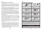
Connection and Use of Safety Valve:
The safety valve should be connected to the cold water inlet pipe. Please check
carefully if the direction is correct after installation. The correct direction of installation
is that the arrowhead on the safety valve should be pointed to the water heater.
Please connect the drain hose to the safety valve. Connect one end of the hose to the
safety valve vent and the other end to the sewage drain. The hose can be cut short or
extended as necessary. The hose shall be installed as inclined downward.
The water may drip from the discharge pipe of the pressure relied device and that this
pipe must be installed in a continuously downward direction and in a frost-free
environment. Check safety valve once a month as follow: move the small handle of
safety valve, if there's water flowing out, safety valve is normal; if there's no water flow,
please contact local after-sales service station.
The pressure relief device is to be operated regularly to remove lime deposits and to
verify that it is not blocked.
1. Indication Area
2. Mode selection Button
3.
4. Set Button
5.
6. On/Off Button
7. Confirmation Button
8.
Temperature and Clock Time
Increase Button
Temperature and Clock Time
Decrease Button
Power Level Selection Button