


#41311 Page 4
Assembly and Operating Instructions
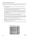
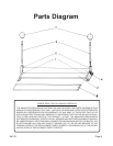
The 30” Bending Brake requires some minor assembly as described below. Please refer to the
parts diagram on page 5 and the part number listing shown below when reading these instruc-
tions.
The Stand (#1) should be secured to a work bench using the mounting holes and 4
bolts (3/8” diameter).
Each Handle Ball (#7) should be attached to the Handle Lever (#6) and the Handle
Levers should be placed into the Handle Sockets (#5). The Handle Levers are not de-
signed to be permanently mounted into the Handle Sockets.
To use the Bending Brake, lower the Handle Lever until the Moving Plate is parallel to
the work bench. Position the material to be bent on the Supporting Plate (#2) and the
Moving Plate and properly align with the edge to be bent up against the back edge of
the Supporting Plate.
Place and secure the Pressing Plate (#3) on top of the Supporting Plate with the back
edge of Pressing Plate aligned with back edge of Supporting Plate.
Note: To insure a proper bend, leave a 1/8” gap for 18 gauge material. For thicker ma-
terial, this gap will increase. It is suggested that you bend a scrap piece of material rst
to verify the correct material position. It is also recommended that the material be held
in place with C-clamps or other appropriate holding devices.
Raise the two Handle Levers to bend the material to the desired angle.
WARNING! When using the Bending Brake keep ngers clear of the Supporting Plate
and Moving Plate to avoid personal injury.
When the Bending Brake is not in use, it should be covered and stored in a dry location.
1.
2.
3.
4.
5.
6.
7.
8.
Part Number Listing
Part Description Q’ty
1 Stand 1
2 Supporting Plate 1
3 Pressing Plate 1
4 Moving Plate 1
5 Handle Sockets 2
6 Handle Lever 2
7 Handle Ball 2
REV 00f,02e