


SKU 90234 PAGE 11
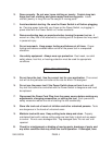
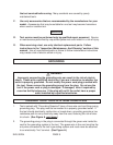
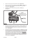
4. Make sure the “On/Off” Pressure Switch (part #66) is DOWN in its OFF position.
Then, plug the Power Cord (part #64) into the nearest 120 volt, grounded,
electrical outlet. (See Figure F.)
5. Pull UP on the “On/Off” Pressure Switch (part #66) to its ON position.
(See Figure F.)
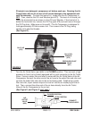
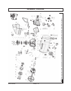
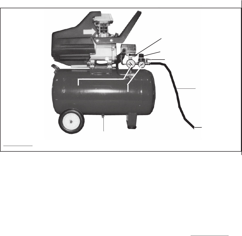
AIR OUTLET VALVE (#69)
AIR HOSE
(NOT INCLUDED)
ATTACH TO
AIR TOOL.
TANK DRAIN VALVE
(#59)
AIR OUTLET
PRESSURE GAUGE
(#71)
TANK
PRESSURE GAUGE
(#65)
PRESSURE REGULATOR (#70)
PRESSURE SWITCH (#66)
3. Make sure the Tank Drain Valve (part #59) is closed. (See Figure F.)
FIGURE F
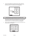
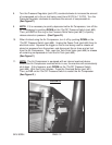
6. Allow the Air Compressor to build up from 85 PSI to 115 PSI as indicated on the
Tank Pressure Gauge (part #65). When the air pressure reaches 85 PSI, open
the Air Outlet Valve (part #69) to allow the air hose and air tool to become pres-
surized. (See Figure F.)
7. As long as the “On/Off” Pressure Switch (part #66) is in its ON position the opera-
tion of the Air Compressor is automatic, controlled by an internal pressure switch.
The Air Compressor will turn on automatically when the air pressure drops to 85
PSI as indicated on the Tank Pressure Gauge (part #65), and will turn off auto-
matically when the air pressure reaches 115 PSI as indicated. IMPORTANT:
The internal pressure switch is adjustable, but changes to the air pressure levels
should not be done. Any change to the automatic pressure levels will cause
additional stress on the motor which may result in shortened motor life and will
void the warranty. (See Figure F.)
“ON/OFF”