


306531 13
Air Motor Service
Before you start:
D Have all necessary parts on hand. Always replace
the glands and bearing when replacing the pack-
ings. Use all the parts in the repair kits for the best
results. See page 18 to order the kits.
D Air Motor Repair Kit 206728. Parts included in
this kit are marked with a dagger, (for example,
36
†), in the text and drawings.
D Displacement Pump Repair Kit 206925. Parts
included in this kit are marked with one asterisk,
(i.e., 6*), in the text and drawings.
D Two accessory tools should be ordered. Use
Padded Pliers, 207579, to grip the trip rod without
damaging its surface. Use Gauge, 171818, to
ensure the proper clearance between the poppets
and seat of the transfer valve.
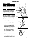
Air Motor & Throat Disassembly
WARNING
To reduce the risk of serious injury whenever you
are instructed to relieve pressure, always follow the
Pressure Relief Procedure on page 8.
1. Flush the pump.
2. Relieve the pressure before proceeding.
3. Disconnect the hoses, remove the pump from its
mounting, and clamp the air motor base (55) in a
vise.
4. Use a strap wrench on the riser tube (12) to screw
it out of the air motor base (55).
5. Pull the connecting rod (10) down as far as it will
go.
6. Use a hammer and punch to remove the roll pin
(4). Unscrew the connecting rod (10). See Fig. 6.
CAUTION
Do not damage the plated surface of the trip rod (54).
Damaging the surface of the trip rod can result in erratic
air motor operation. Use the special Padded Pliers,
Part Number 207579, to grasp the rod.
7. Manually push up on the piston rod (41) to move
the piston assembly (59) up as far as it will go.
Unscrew the cap nut (47). Pull the nut up. Grip the
trip rod (54) with padded pliers, and screw the nut
off the rod. See Fig. 6.
CAUTION
To avoid damaging the cylinder wall, lift the
cylinder (51) straight up off the piston (59). Never tilt the
cylinder as it is being removed.
8. Remove the six screws (25). See Fig. 6. Pull the
cylinder (51) straight up off the piston (59).
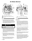
9. Use a screwdriver to push down on the trip rod
yoke (28), and snap the toggles down. See Fig. 7.
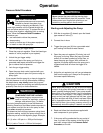
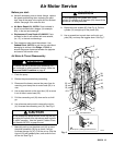
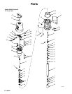
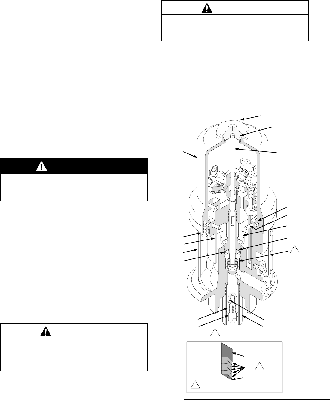
Fig. 6
25
59
51
47
55
27
54
4*
10
41
43
49*
42
44*
50*
38
39†
48*
04210B
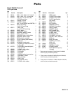
1
2
2
Lips of v-packings must face down.
1 See detail below.
12