


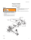
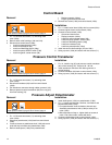
Pressure Control
14 310893L
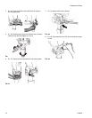
Control Board
Removal
1. FIG. 14. Remove two screws (71) and swing down
cover (130a)
2. Remove strain relief bushings (130r and 123).
3. Disconnect at control board (130b):
• Lead from potentiometer (130d)
• Lead from transducer (66)
• Lead from WatchDog switch (130g)
• Lead from pump ON/OFF switch (130f)
• Lead from gallon counter sensor (39)
• Display connector (130m)
• Engine, ground and clutch wires
4. Remove four screws (130c) and control board (130b).
Installation
1.
FIG. 14
. Install control board (130b) with four screws (130c).
2. Connect engine wires to control board (130b).
3. Connect at control board (130b):
• Ground and clutch wires
• Display connector (130m)
• Lead from gallon counter sensor (39)
• Lead from pump ON/OFF switch (130f)
• Lead from WatchDog switch (130g)
• Lead from transducer (66)
• Lead from potentiometer (130d)
4. Install new strain relief bushings (123 and 130r).
5. Swing up cover (130a) and secure with two screws (71).
Pressure Control Transducer
Removal
1. FIG. 14. Remove two screws (71) and swing down
cover (130a)
2. Disconnect transducer (66) lead from control board
(130b).
3. Pull transducer connector through rubber grommet (113).
4. Remove pressure control transducer (66) and o-ring (67)
from filter housing (72).
Installation
1. FIG. 14. Install o-ring (67) and pressure control transducer
(66) in filter housing (72). Torque to 35 - 45 ft-lb.
2. Install transducer connector and rubber grommet in
control housing.
3. Connect transducer (66) lead to control board (130b).
4. Swing up cover (130a) and secure with two screws (71).
Pressure Adjust Potentiometer
Removal
1. FIG. 14. Remove two screws (71) and swing down
cover (130a)
2. Disconnect potentiometer (130d) lead from control board
(130b).
3. Loosen set screws on potentiometer knob (130h) and remove
knob, shaft nut, lock washer and potentiometer (130d).
4. Remove shaft spacer (130e) from potentiometer.
Installation
1. Install shaft spacer (130e) on potentiometer (130d).
2. FIG. 14. Install potentiometer, shaft nut, lock washer and
potentiometer knob (130h).
a.Turn potentiometer shaft clockwise to internal stop.
Assemble potentiometer knob (130h) to strike pin on
cover (130a).
b.After adjustment of step a., tighten both set screws in
knob 1/4 to 3/8 turn after contact with shaft.
3. Connect potentiometer lead to control board (130b).
4. Swing up cover (130a) and secure with two screws (71).
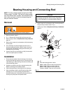
WARNING
Read Injection Hazard, page 3; Burn Hazard, page 4
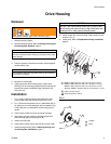
WARNING
Read Injection Hazard, page 3; Burn Hazard, page 4
WARNING
Read Injection Hazard, page 3; Burn Hazard, page 4