


16
English
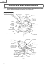
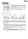
Screw Holder
Knob
Workpiece
Vise
Plate
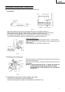
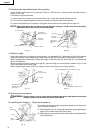
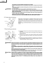
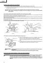
1. Switch operation
The trigger switch lock-off button is designed to prevent inadvert-
ent operation of the power tool. To operate the power tool, it is nec-
essary to first fully insert the lock-off button into the hole on the
handle as shown in Fig. 17.
The trigger switch will not operate unless the lock-off button has
been pushed in.
When the trigger switch is released, the power goes off and the
lock-off button automatically returns to its initial position, locking
the trigger switch.
Fig. 17
WARNING: Always remove the lock-off button from the handle when the power tool is not in
use. This will ensure that the power tool cannot be turned on accidentally or by
someone (especially a child) who is not qualified to use the power tool. If the lock-off
button is left in the handle, serious personal injury can result. Since the lock-off button
fits rather tightly, it may be necessary to turn it to the left and right during mounting
and removing.
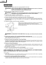
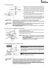
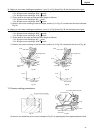
2. Using the Vise Assembly (Standard accessory)
The vise assembly can be mounted on either the left fence (Fence
(B)) or the right fence (Fence (A)), and can be raised or lowered
according to the height of the workpiece.
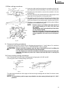
To raise or lower the vise assembly, first loosen the 8mm knob
bolt. As shown in Fig. 18, the vise shaft has three locking grooves
into which the tip of the 8mm knob bolt is designed to fit in order
to lock the screw holder in the desired position.
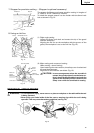
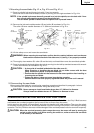
To ensure that the tip of the 8mm knob bolt is properly aligned
with the desired locking groove on the vise shaft, simply align the
upper surface of the fence to either of two grooves on the vise
shaft surface or to the lower surface of the screw holder.
Therefore, the vise assembly can be attached in either of three
positions to ensure proper height adjustment.
After adjusting the height, firmly tighten the 8mm knob bolt; then
turn the upper knob, as necessary, to securely attach the workpiece
in position.
Fig. 18
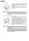
CAUTION: Always confirm that the motor head (see Fig. 1) does not contact the vise assembly
when it is lowered for cutting. If there is any danger that it may do so, loosen the
8mm knob bolt slightly and move the vise assembly to a position where it will not
contact the saw blade.
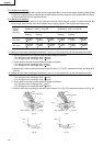
In case of compound cutting of left bevel angle and left miter angle, a workpiece of
up to 45mm can be fixed with a vise assembly mounted on the left side. In case the
workpiece height exceeds 45mm, mount the ivse assembly on the opposite side of
the inclination of the motor head. For other compound cutting (left bvel + right miter,
right bevel + left miter and right bevel + right miter), mount the vise asembly on the
opposite side of the inclination of the motor head to avoid the contact of the vise
assembly with the motor head.
Vise Shaft
6mm
Knob Bolt
V Shape
Groove
Fence
Handle
Trigger
Switch
Lock-off Button
Hole
8mm Knob Bolt