


–
12
–
English
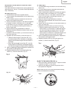
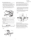
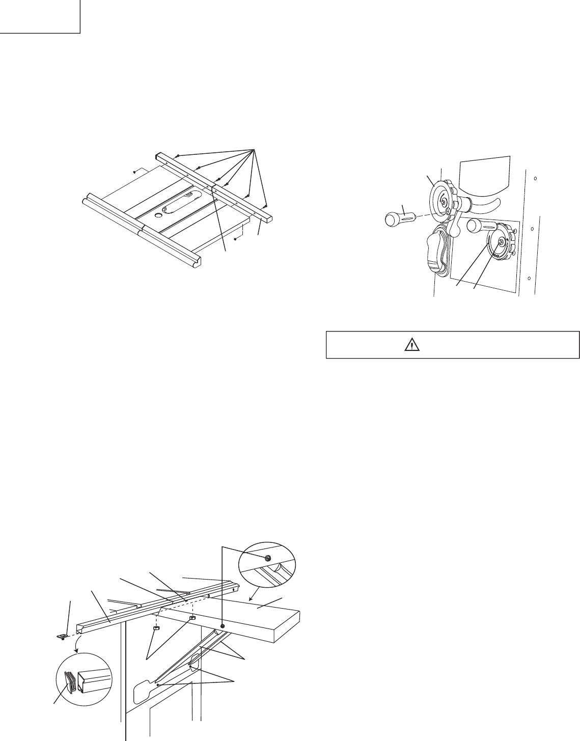
BLADE RAISING HANDWHEEL (FIG. D)
Thread the blade handwheel handle (1) into blade
raising handwheel (2) and tighten.
BLADE TILTING HANDWHEEL (FIG. D)
1. Attach the blade tilting handwheel (3) to the elevation
screw at the front of the saw.
2. Attach and tighten the dome nut (4) at the end of the
shaft.
Fig.
D
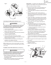
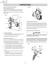
BLADE GUARD ASSEMBLY (FIG. E, F)
To avoid injury from an accidental start, make sure
the switch is in the OFF position and the plug is
disconnected from the power source outlet.
• When installing the blade guard, cover the blade
teeth with a piece of folded cardboard to protect
yourself from possible injury.
• Never operate this machine without the safety
guard in place for all through sawing operations.
Installing the blade guard assembly (Fig. E)
1. Remove the table insert.
2. Unlock the blade bevel lock knob (1).
3 With the blade elevation handwheel (2), raise the
blade to the maximum height.
4. Using the blade tilting handwheel, tilt the blade to 45
o
on the bevel scale.
5. Lock the blade tilt locking knob.
6. Locate the splitter assembly mounting bracket in
back of the blade.
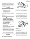
7. Cover the blade teeth with a folded cardboard or
position the plastic blade guard over the blade to
protect your hands.
8. Place the two kickback pawls (4) toward the rear of
the table, and align the splitter mounting holes to the
holes in the bracket.
9. Place the steel fl at washers (6) on the two bolts (5)
and tread the bolts into the holes.
NOTE
: Make sure the “anti-kick back pawls” do not get
caught between the insert and the guard, but rest on top
of the insert.
WARNING
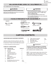
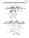
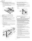
Assembly the rear table rail (Fig. B-2)
6. Attach the middle plug (1) to the rear table rails (2).
7. Place the rear table rails on the saw table, aligning
with the holes in each rail.
8. Place the bolts (3) and tread in the holes; tighten the
bolts and check the alignment again.
Fig.
B-2
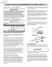
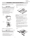
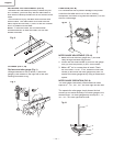
ASSEMBLY THE REAR TABLE EXTENSION
(FIG. C)
NOTE: The maximum load for the rear table
extension is 30 kg.
1. Insert the support rods (1) into the slot on the body
shell.
Pla
ce screws (2) and tighten.
2. Attac
h the rear table extension (3) to the support
rods (1).
Place screws (4) and tighten.
3. Place the screws (9) to the slot of the rear table reails
(8).
4. Attach the side cover (10) to the rear table reails (8).
5. Tighten the nuts (7).
6
. Align the triangle (5) on the rear table extension and
the middle plug (6).
7. Loosen the nuts (7) and screws (4) to adjust the rear
table extension (3)
f
or alignment.
Fig. C
1
2
4
3
1
2
3
4
5
6
7
9
8
10
3
1
2