


English
13
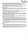
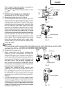
The L-side of the push button is pushed to
turn the bit counterclockwise.
(The
L
and
R
marks are provided on the
body.)
10.Attaching the angle unit. (Optional
accessory for D13VF and D13VG)
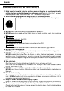
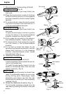
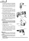
(1) Removing chuck from drill (Fig. 8)
⅜ To remove the chuck from the drill, open the
chuck jaws as far as possible and turn out the
locking screw (left hand thread). This screw
locks the chuck to the spindle. And hold the
drill so that only the chuck rests firmly and
squarely on the edge of a solid bench. Install
the hex. bar wrench into the chuck. Turn the
chuck until the wrench is at about a 30° angle
to the bench top and strike the wrench sharply
with a hammer so the chuck turns in the
counterclockwise direction (viewed from the
front side). This should loosen the chuck
from the spindle which has a right hand
thread and you will be able to remove the
chuck by hand.
CAUTION:
If the chuck cannot be removed by striking the wrench, don’t strike the wrench forcibly
and send the drill to a HITACHI AUTHORIZED SERVICE CENTER.
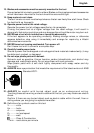
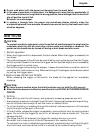
(2) Attaching the angle unit.
⅜ After removing the chuck, engage the
coupling to the drill spindle. Fit the joint
sleeve to the gear cover, attach the angle unit
to the other end of the joint sleeve, and turn
the angle unit slightly in either direction so
the hex. hole in the coupling engages the
hex. portion of the angle unit spindle. Adjust
the direction of the angle unit and tighten the
joint sleeve by clamping bolts.
Tighten two clamping bolts equally and
gradually in turn with a torque of 61-70 In-
lbs. (70-80kg-cm) (extent of force which can
be subjected by only a wrist with the open
end wrench provided to tight clamping bolts.).
(Fig. 9)
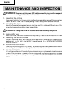
⅜ To operate the angle unit at low speed, attach
the chuck to the angle unit spindle at the side
marked “LOW” and secure the locking screw.
At this setting, the drilling speed is decreased
to about 70% and the drilling torque increased
to about 150%. (Fig. 10)
Fig. 7
L
mark
R
mark
Siwtch Trigger
Fig. 8
Hex. Bar
Wrench
Locking Screw
Loosen
Fig. 10
Low Speed
Fig. 9
Angle
Unit
Joint
Sleeve Coupling
Clamping Bolt