


4
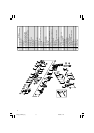
Fig. 6
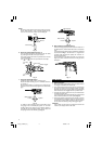
8. High-speed/Low-speed changeover
Prior to changing speed, ensure that the switch is in
the OFF position, and the drill has come to a complete
stop.
To change speed, rotate the gear shift dial as indicated
by the arrow in Fig. 7. The numeral “1” engraved on
the drill body denotes low speed, the numeral “2”
denotes high speed.
If it is hard to turn the gear shift dial, turn the chuck
slightly in either direction and then turn the gear shift
dial again.
Fig. 7
HOW TO USE
1. Switch operation
⅜ When the trigger is depressed, the tool rotates. When
the trigger is released, the tool stops.
⅜ The rotational speed of the drill can be controlled by
varying the amount that the trigger switch is pulled.
Speed is low when the trigger switch is pulled slightly
and increases as the trigger switch is pulled more.
⅜ The desired rotation speed can be pre-selected with
the speed control dial.
Turn the speed control dial clockwise for higher speed
and counterclockwise for lower speed (Fig. 8).
⅜ Pulling the trigger and pushing the stopper, it keeps
the switched-on condition which is convenient for
continuous running. When switching off, the stopper
can be disconnected by pulling the trigger again.
CAUTION
If the L-side of push button is pressed for reverse bit
rotation, the stopper cannot be used.
NOTE
When the sleeve does not become loose any further,
fix the side handle to ring, hold side handle firmly,
then turn the sleeve to loosen by hand (Fig. 3).
Fig. 3
6. Check the rotational direction (Fig. 4)
The bit rotates clockwise (viewed from the rear side)
by pushing the R-side of the push button.
The L-side of the push button is pushed to turn the bit
counterclockwise.
(The
L
and
R
marks are provided on the body.)
Fig. 4
7. Fixing the side handle (Fig. 5)
Attach the side handle to the mounting part.
Rotate the side handle grip in a clockwise direction
to secure it.
Set the side handle to a position that is suited to the
operation and then securely tighten the side handle
grip.
Fig. 5
To attach a depth gauge on the side handle, insert
the gauge into the U-shaped groove on the side
handle, adjust the position of the depth gauge in
accordance with the desired depth of the hole, and
firmly tighten the side handle grip (Fig. 6).
L
mark
Push button
Switch trigger
R
mark
Side handle
Loosen Tighten
Side handle
Loosen Tighten
Depth gauge
Ring
Side handle
Loosen
Sleeve
Gear
shift dial
01Eng_D13VB3_Eng 4/20/09, 17:194