


8
English
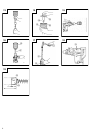
(3) When the hole depth reaches approximately 5 mm,
the hole position can be determined. Then remove
the center pin and guide plate from the core bit
and continue the hole drilling job.
CAUTION
When removing the center pin and guide plate,
always disconnect the plug from the receptacle.
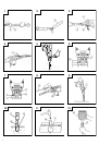
3. How to dismount the core bit
⅜ By holding the drill (with the core bit inserted) in
an upward position, drive the drill to repeat
hammering operation two or three times, whereby
the screw is loosened and the drill becomes ready
for disassembly. (Fig. 16)
⅜ Remove the core bit shank from the drill, hold the
core bit with one hand, and strongly strike the head
of the spline portion of the core bit shank with a
manual hammer two or three times, whereby the
round head screw is loosened and the drill is ready
for disassembly. (Fig. 17)
HOW TO REPLACE GREASE
This machine is of full air-tight construction to protect
against dust and to prevent lubricant leakage.
Therefore, the machine can be used without lubrication
for long periods. Replace the grease as described
below.
1. Grease replacement period
After purchase, replace grease after every 6 months
of usage. Ask for grease replacement at the nearest
Hitachi Authorized Service Center. Proceed for
replacement of grease.
2. Grease replenishment
CAUTION
Before replenishing the grease, turn the power off
and pull out the power plug.
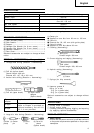
(1) Remove the crank case cover and wipe off the
grease inside. (Fig. 18)
(2) Supply 20g of Hitachi Electric Hammer Grease A
(Standard accessory, contained in tube) to the crank
case.
As the tube contain 30g of grease, supply 2/3 of
the contained grease.
(3) After replenishing the grease, install the crank case
cover securely.
NOTE
The Hitachi Electric Hammer Grease A is of the low
viscosity type. If necessary purchase from a Hitachi
Authorized Service Center.
MAINTENANCE AND INSPECTION
1. Inspecting the tool
Since use of a dull tool will degrade efficiency and
cause possible motor malfunction, sharpen or
replace the tool as soon as abrasion is noted.
2. Inspecting the mounting screws:
Regularly inspect all mounting screws and ensure
that they are properly tightened. Should any of the
screws be loose, retighten them immediately. Failure
to do so could result in serious hazard.
3. Maintenance of the motor
The motor unit winding is the very “heart” of the
power tool. Exercise due care to ensure the winding
does not become damaged and/or wet with oil or
water.
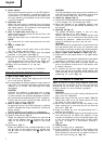
4. Inspecting the carbon brushes (Fig. 19)
The Motor employs carbon brushes which are
consumable parts. When they become worn to or
near the “wear limit”, it could result in motor trouble.
When an auto-stop carbon brush is equipped, the
motor will stop automatically. At that time, replace
both carbon brushes with new ones which have the
same carbon brush Numbers shown in the figure.
In addition, always keep carbon brushes clean and
ensure that they slide freely within the brush holders.
5. Replacing carbon brushes
Loosen the two set screws and remove the tail
cover. Remove the brush caps and carbon brushes.
After replacing the carbon brushes, tighten the brush
caps securely and install the tail cover with securely
tightening two set screws.
NOTE
Due HITACHI’s continuing program of research and
development, the specifications herein are subject to
change without prior notice.
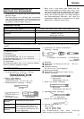
IMPORTANT
Correct connection of the plug
The wires of the main lead are coloured in accordance
with the following code:
Blue: — Neutral
Brown: — Live
As the colours of the wires in the main lead of this
tool may not correspond with the coloured markings
identifying the terminals in your plug proceed as
follows:
The wire coloured blue must be connected to the
terminal marked with the letter N or coloured black.
The wire coloured brown must be connected to the
terminal marked with the letter L or coloured red.
Neither core must be connected to the each terminal.
NOTE
This requirement is provided according to BRITISH
STANDARD 2769: 1984.
Therefore, the letter code and colour code may not be
applicable to other markets except The United Kingdom.
Information concerning airborne noise and vibration
The measured values were determined according to
EN50144.
The typical A-weighted sound pressure level: 89 dB (A)
The typical A-weighted sound power level: 102 dB (A)
Wear ear protection.
The typical weighted root mean square acceleration
value: 10 m/s
2