


5
English
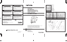
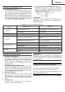
SPECIFICATIONS
Model FCJ55VA FCJ55
Voltage (by areas)* (110V, 115V, 120V, 127V, 220V, 230V, 240V)
Power input 400W*
Wood: 55mm
Max. cutting depth
Mild steel: 3mm
No-load speed 0 ~ 3000/min 3000/min
Stroke 18mm
Min. cutting radius 25mm
Weight (without cord) 1.4kg
* Be sure to check the nameplate on product as it is subject to change by areas.
STANDARD ACCESSORIES
(1) Blade No.31................................................................. 1
For cutting thick lumber
(2) Splinter guard............................................................. 1
(3) Chip cover ...................................................................1
(4) Hexagonal bar wrench............................................... 1
Standard accessories are subject to change without
notice.
OPTIONAL ACCESSORIES (sold separately)
(1) Blades, No.1 ~ No.6, 31*
* No.31 Blade is a standard accessory.
(2) Guide
(3) Dust collector
Optional accessories are subject to change without notice.
APPLICATIONS
⅜ Cutting various lumber and pocket cutting
⅜ Cutting mild steel plate, aluminum plate, and copper
plate
⅜ Cutting synthetic resins, such as phenol resin and
vinyl chloride
⅜ Cutting thin and soft construction materials
PRIOR TO OPERATION
1. Power source
Ensure that the power source to be utilized conforms
to the power requirements specified on the product
nameplate.
2. Power switch
Ensure that the power switch is in the OFF position. If
the plug is connected to a receptacle while the power
switch is in the ON position, the power tool will start
operating immediately, which could cause a serious
accident.
3. Extension cord
When the work area is removed from the power
source, use an extension cord of sufficient thickness
and rated capacity. The extension cord should be
kept as short as practicable.
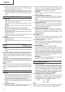
MOUNTING THE BLADE
1. Use the accessory hexagonal bar wrench to loosen
the blade set screws on the set ring, as shown in
Fig. 1.
2. Holding the blade with its cutting edge facing the
front, insert the mounting portion of the blade into
the plunger groove until it touches the bottom of the
groove.
3. As shown in Fig. 1, firmly clamp the side screw.
CAUTION
⅜ Loosened set screws may cause the blade to be
damaged. Always ensure that the set screws are
securely tightened. Always ensure that the plunger
groove is clean and clear of sawdust to ensure proper
blade mounting and set screw clamping.
ADJUSTING AND REMOVING THE GUIDE
ROLLER
1. Adjusting the guide roller
The guide roller, shown in Fig. 2, is employed to
prevent the blade from snapping. Prior to use, adjust
guide roller in accordance with the following
procedures:
(1) Loosen the holder set screw with the accessory
hexagonal bar wrench.
(2) Gently slide the guide roller until the roller groove
lightly touches the back of the blade.
NOTE
On delivery from the factory, there is a gap of about
3mm between the roller and blade.
(3) Firmly tighten the holder set screw.
CAUTION
⅜ The guide roller can be used only for Blades that
have a straight line on the rear that is longer than
50mm. (Fig. 3A and 3B) When using other types
of blades (Fig. 3C), slide the guide roller in
backwards so that the guide roller does not contact
the blade.
⅜ When cutting thick boards or performing
continuous cutting operations, use the blade
shown in the Fig. 3A, 3B and be sure to set the
guide roller.
2. Removing the guide roller
The guide roller can be removed from the jig saw
as follows: