


5
4. Fitting and adjusting the wheel guard
The wheel guard is a protective device to prevent
injury should the depressed center wheel be
shattered during operation. Ensure that the wheel
guard is properly fitted and fastened before
commencing grinding operation.
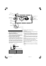
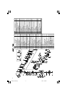
[How to attach and adjust the wheel guard] (Fig. 1)
⅜ Set the wheel ass’y to the packing gland.
⅜ Tighten M5 screw to secure the wheel guard while
the lever is in closed position.
⅜ Perform the adjustment of the wheel guard while
the lever is released. (Loosen M5 screw and readjust
if the wheel guard does not rotate smoothly.)
⅜ After adjustment, if grinder operation is required,
perform the operation only after setting the lever
in closed position.
⅜ Lubricate the sliding section of the set piece (B) and
the lever if the lever does not move smoothly.
5. Ensure that mounted wheels and points are fitted
in accordance with the manufacturer’s instructions.
Ensure that the depressed center wheel to be utilized
is the correct type and free of cracks or surface
defects. Also ensure that the depressed center wheel
is properly mounted and the wheel nut is securely
tightened. Refer to the section on “ASSEMBLING
AND DISASSEMBLING ACCESSORIES”.
Ensure that blotters are used when they are provided
with the bonded abrasive product and when they
are required.
Do not use separate reducing bushings or adaptors
to adapt large hole abrasive wheels.
For tools intended to be fitted with threaded hole
wheel, ensure that the thread in the wheel is long
enough to accept the spindle length.
Do not use cutting off wheel for side grinding.
6. Conducting a trial run
Ensure that the abrasive products is correctly
mounted and tightened before use and run the tool
at no-load for 30 seconds in a safe position, stop
immediately if there is considerable vibration or if
other defects are detected.
If this condition occurs, check the machine to
determine the cause.
7. Confirm the push button.
Confirm that the push button is disengaged by
pushing push button two or three times before
switching the power tool on (See Fig. 1).
8. Fixing the side handle.
Screw the side handle into the gear cover.
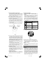
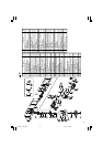
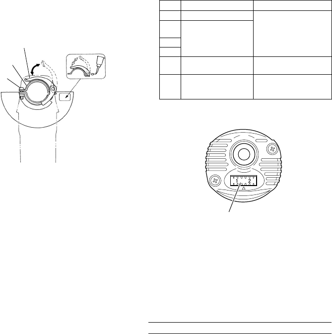
9. Adjusting the number of revolution (EXCEPT OF
G13YF)
Above models are equipped with an electronic
infinite-variable-speed drive and can change the
number of revolution according to a use.
If you turn and set the dial scale (Fig. 2) to 6, the
number of revolution increases, and if you turn and
set it to 1, the number of revolution decreases.
Before use, set the number of revolution using the
dial. In so doing, refer to the following table as
a rough guide.
NOTE: Use caution not to turn the dial scale to any value
below 1 or above 6.
10. Caution when using near welding equipment
When using the grinder in the immediate vicinity
of welding equipment, the rotational speed may
become unstable. Do not use the grinder near
welding equipment.
11. RCD
The use of a residual current device with a rated
residual current of 30 mA or less at all times is
recommended.
PRACTICAL GRINDER APPLICATION
1. Pressure
Do not apply the grinding wheel strongly to the
grinding surface. The grinder makes use of electronic
circuit, so during application of load rotates at high
speed, so ample grinding effect can be obtained by
applying light pressure. If a strong grinding pressure
or other abnormal load is applied, the overload
protection circuit will operate and make the grinder
stop rotating, so please stop applying load
immediately. Following this, switching the power
OFF and then ON again, will cause the rotation to
increase to the regular speed.
Dial Use Tools
1 Polishing, finishing
2
Removal of paint or
coat
3 Removal of rust
4 Removal of burrs
5
Grinding
Rough grinding
6 Cutting
Radial grinding disc
Sanding disc
Depressed center
wheel
Depressed center
wheel
Diamond wheel
M5 screw
Lever
Set piece (B)
Fig. 1
Fig. 2
Dial
01Eng_G12VA_Eng 1/12/11, 4:42 PM5