


11
English
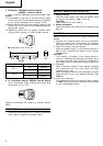
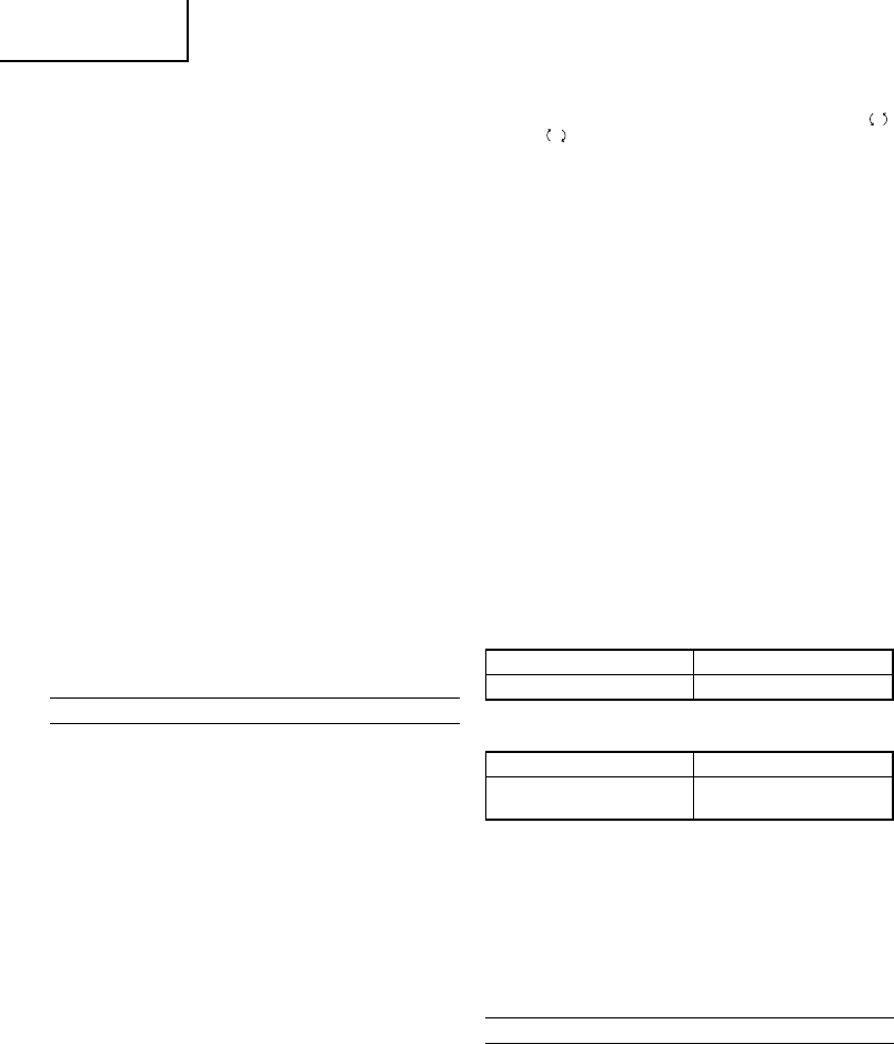
The L-side of the push button is pushed to turn the
bit counterclockwise. (See Fig. 11). (The
L
and
R
marks are engraved on the body.)
CAUTION
The push button can not be switched while the
impact driver is turning. To switch the push button,
stop the impact driver, then set the push button.
3. Switch operation
⅜ When the trigger switch is depressed, the tool
rotates. When the trigger is released, the tool stops.
⅜ The rotational speed can be controlled by varying
the amount that the trigger switch is pulled. Speed
is low when the trigger switch is pulled slightly and
increases as the trigger switch is pulled more.
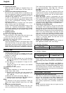
4. Tightening and loosening bolts
A hex socket matching the bolt or nut must first
be selected. Then mount the socket on the anvil,
and grip the nut to be tightened with the hex socket.
Holding the wrench in line with the bolt, press the
power switch to impact the nut for several seconds.
If the nut is only loosely fitted to the bolt, the bolt
may turn wit the nut, therefore mistaking proper
tightening. In this case, stop impact on the nut and
hold the bolt head with a wrench before restarting
impact, or manually tighten the bolt and nut to
prevent them slipping.
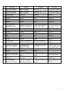
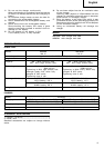
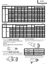
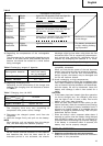
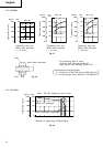
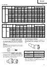
5. Number of bolt tightened possible
Please refer to the table below for the number of
bolt tightened possible with one charge.
For WR12DM (EB1230HL)
For WR9DM (EB930H)
These values may vary slightly, according to
surrounding temperature and battery characteristics.
NOTE
The use of the battery EB1230HL and EB930H in
a cold condition (below 0 degree Centigrade) can
sometimes result in the weakened tightening torque
and reduced amount of work. This, however, is a
temporary phenomenon, and returns to normal when
the battery warms up.
OPERATIONAL CAUTIONS
1. Resting the unit after continuous work
After use for continuous bolt-tightening work, rest
the unit for 15 minutes or so when replacing the
battery. The temperature of the motor, switch, etc.,
will rise if the work is started again immediately
after battery replacement, eventually resulting in
burnout.
NOTE:
Do not touch the hammer case, as it gets very hot
during continuous work.
Bolt used No. of tightenings
M16 × 55 (F10T) Approx. 135
2. Checking the battery
Make sure that the battery is installed firmly. If it
is at all loose it could come off and cause an
accident.
3. Selecting the socket matched to the bolt
Be sure to use a socket which is matched to the
bolt to be tightened. Using an improper socket will
not only result in insufficient tightening but also in
damage to the socket or nut.
A worn or deformed hex. or square-holed socket
will not give an adequate tightness for fitting to the
nut or anvil, consequently resulting in loss of
tightening torque.
Pay attention to wear of socket hole, and replace
before further wear has developed.
Finally, install the socket prescribed in Item 4. The
section on “Optional Accessories” details the
relationship between bolt sizes and sockets. Sockets
are named according to the dihedral width of the
hexagonal hole.
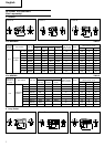
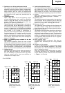
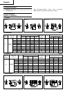
4. Installing a socket
Select the socket to be used.
ⅷ Pin, O-ring type (Fig. 4 and 5)
(1) Align the hole in the socket with the hole in the
anvil and insert the anvil into the socket.
(2) Insert the pin into the socket.
(3) Attach the ring to the groove on the socket.
ⅷ Plunger type (Fig. 6)
Align the plunger located in the square part of the
anvil with the hole in the hex. socket. Then push
the plunger, and mount the hex. socket on the anvil.
Check that the plunger is fully engaged in the hole.
When removing the socket, reverse the sequence.
HOW TO USE
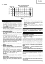
1. Using the convenient hook
The convenient hook can be installed on the right
or left side and the angle can be adjusted in 5 steps
between 0° and 80°.
(1) Operating the hook
(a) Pull out the hook toward you in the direction
of arrow (A) and turn in the direction of arrow
(B). (Fig. 7)
(b) The angle can be adjusted in 5 steps (0°, 20°,
40°, 60°, 80°).
Adjust the angle of the hook to the desired
position for use.
(2) Switching the hook position
CAUTION:
Incomplete installation of the hook may result in
bodily injury when used.
(a) Securely hold the main unit and remove the
screw using a slotted head screwdriver or a
coin. (Fig. 8)
(b) Remove the hook and spring. (Fig. 9)
(c) Install the hook and spring on the other side and
securely fasten with screw. (Fig. 8)
NOTE:
Pay attention to the spring orientation. Install the
spring with larger diameter away from you. (Fig.
10)
2. Check the rotational direction
The bit rotates clockwise (viewed from the rear
side) by pushing the R-side of the push button.
Bolt used No. of tightenings
High tension bolt
Approx. 135
M12 × 45