


OM-928 Page 17
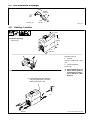
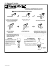
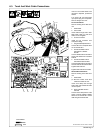
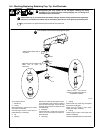
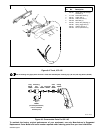
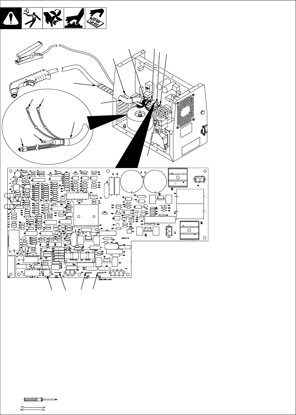
6-3. Torch And Work Cable Connections
If torch or work cable needs to be
removed or replaced, proceed as
follows:
Turn power Off, and disconnect
input power plug from receptacle.
Remove wrapper from unit.
Torch Connections
Remove existing torch cable from
unit.
1 Strain Relief
2 Torch Cable
Insert cable through strain relief.
Slide strain relief nut onto torch
cable, but do not tighten.
3 Air Line Connector
Install air line connector onto
compressor fitting.
4 Plug PLG4/Receptacle RC4
Connect PLG4 to receptacle RC4
on circuit board PC1.
5 Female And Male Friction
Terminal RC11/ELECT
WHITE
Connect female friction terminal on
end of white leads to RC11/ELECT
WHITE.
6 Female And Male Friction
Terminal RC7/PILOT RED
Connect female friction terminal on
end red leads to RC7/PILOT RED.
Tighten strain relief nut.
Tighten strain relief around cable.
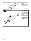
Work Cable Connections
Remove existing work cable from
unit.
7 Strain Relief
. Be sure to allow some work
cable slack inside the unit.
Insert work clamp lead through
strain relief, and install strain relief
into front panel.
8 Work Lead Male Friction
Terminal
Connect work clamp lead to male
friction terminal labeled WORK
LEAD on circuit board PC1. Route
lead along torch lead bundle.
Tools Needed:
5/8 in
4
586
Ref. 803 639-B / Ref. 801 300-B / 199 088
3
2
4
5
6
1
3
7
8
4
6
2
5