


OM-185 480 Page 5
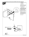
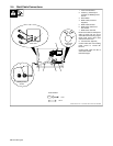
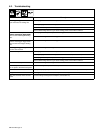
2-3. Voltage Sensing Lead Connections And Motor Start Control Adjustment
ST-801 840 / ST-150 035
1 Center Baffle
2 Circuit Board PC1
3 Jumper Plug
4 Receptacle RC3
Internal (INT) and external (EXT)
are stamped on PC1 just above
RC3. Unit is shipped with jumper
plug in internal (INT) position.
5 Potentiometer R70
6 Voltage Sensing Lead
For constant current welding
(CC), place jumper plug in the
EXT position. Connect voltage
sensing lead to workpiece.
For constant voltage welding (CV),
place jumper plug in the INT posi-
tion. Do not connect voltage sens-
ing lead.
To adjust motor ramp speed, re-
move protective cap (if present),
and adjust potentiometer R70 us-
ing a small nonconductive screw-
driver. Rotating R70 clockwise in-
creases the time it takes the motor
to ramp up to speed.
Reinstall wrapper.
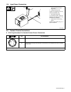
Tools Needed:
1/4 in
Front
1
2
3
4
5
123
INT. EXT.
RC3
CV CC
6
Rear View
For CC operation, connect
voltage sensing lead to
workpiece.
Work