


. A complete Parts List is available at www.HobartWelders.com
OM-230 455 Page 13
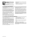
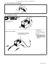
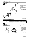
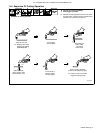
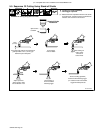
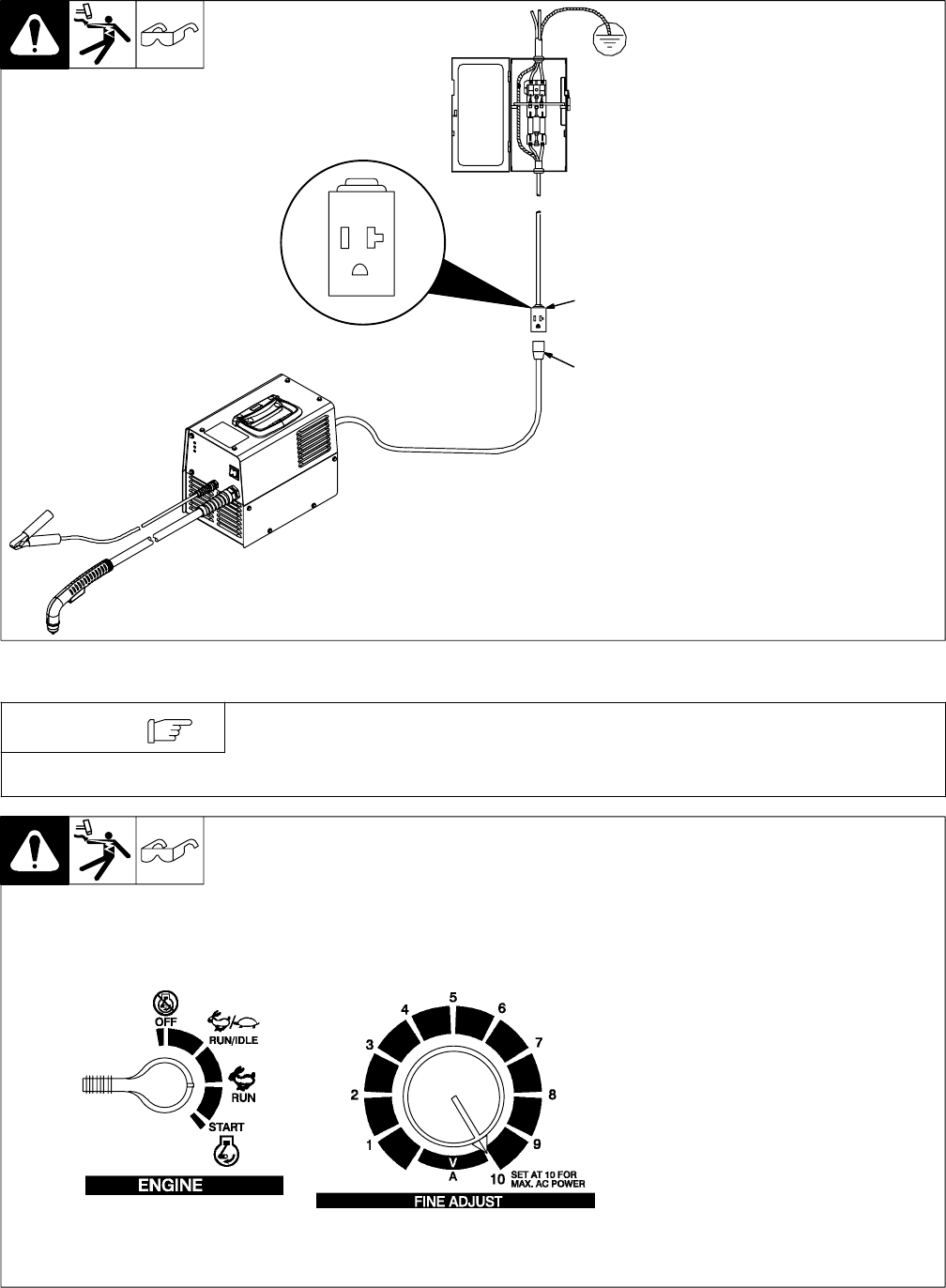
4-9. Connecting Input Power
Ref. 804 852-A / Ref. 803 766-B
Check input voltage available at
site.
1 Grounded Receptacle
A 120 volt, 20 ampere individual
branch circuit protected by
time-delay fuses or circuit breaker
is required (see Section 4-7).
2 Plug From Unit
Connect plug to receptacle. For ex-
tension cord data, see Section 4-8.
Y Special installation may be
required where gasoline or
volatile liquids are present −
see NEC Article 511 or CEC
Section 20.
120 V 20 A
Receptacle
1
2
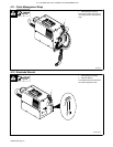
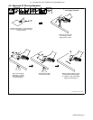
4-10. Generator Or Inverter Requirements
Generator or inverter operation varies by manufacturer. The power light on the
cutter will flash and the unit will not provide output if input voltage drops below 92
volts ac (see Section 6-2).
NOTE
Minimum auxiliary power require-
ment at rated cutting capacity [1/8
in (3.2 mm) mild steel] is 4 KW con-
tinuous/4.5 KW peak at 120 volts
ac.
. The 115 volts ac output of a
brushless generator will momen-
tarily droop when loaded. This
may result in arc outages at the
cutter. Connecting a load, such
as a 500 watt halogen light bulb,
to the 115 volts ac generator
circuit will pre-load the circuit and
may result in less generator
output droop and better cutting
performance.
. For inverter operation, a 200
ampere alternator is recom-
mended for adequate recharg-
ing of the vehicle battery.
Y Engine Control Switch must be set at “RUN”
position − not “RUN/IDLE”.
Y Set generator Fine Adjustment Control
to 10 for maximum auxiliary power.
Generator settings, if applicable.