


OM-945 Page 13
SECTION 5 − INSTALLATION
install2 11/04 − Ref. 800 652 / Ref. 800 477-A / 803 274
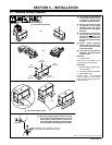
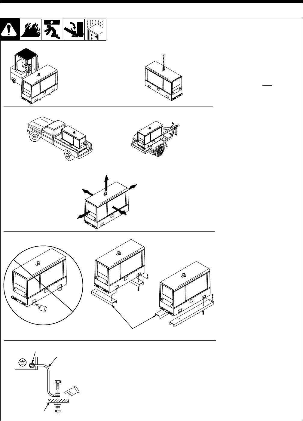
Y Do not weld on base. Welding
on base can cause fuel tank fire
or explosion. Bolt unit down
using holes provided in base.
Y Always securely fasten weld-
ing generator onto transport
vehicle or trailer and comply
with all DOT and other applica-
ble codes.
Y Do not mount unit by support-
ing the base only
at the four
mounting holes. Use cross-
supports to adequately sup-
port unit and prevent damage
to base.
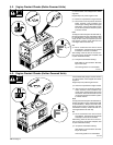
Y Always ground generator
frame to vehicle frame to pre-
vent electric shock and static
electricity hazards.
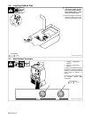
Y If unit does not have GFCI re-
ceptacles, use GFCI-protected
extension cord.
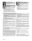
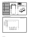
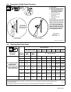
Mounting:
1 Cross-Supports
Mount unit on flat surface or use
cross-supports to support base.
Grounding:
2 Equipment Grounding Terminal
(On Front Panel)
3 Grounding Cable (Not Supplied)
4 Metal Vehicle Frame
Connect cable from equipment
ground terminal to metal vehicle
frame. Use #10 AWG or larger insu-
lated copper wire.
Electrically bond generator frame to
vehicle frame by metal-to-metal contact.
GND/PE
2
3
4
OR
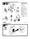
18 in
(460 mm)
18 in
(460 mm)
18 in
(460 mm)
18 in
(460 mm)
18 in
(460 mm)
Movement
Location / Airflow Clearance
Grounding
Y Do not lift unit from end.
5
-1. Installing Welding Generator
Mounting
1
Inadequate support.
Y Do not use flexible mounts.
OR
Y Bed liners, shipping skids, and some running
gears insulate the welding generator from the
vehicle frame. Always connect a ground wire
from the generator equipment grounding termi-
nal to bare metal on the vehicle frame as shown.
OR