


OM-193 471 Page 14
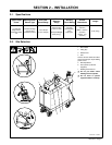
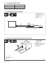
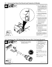
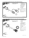
2-9. Interconnecting Power Cord Ground Lead Connection (All Models)
Ref. 802 310
. The interconnecting power
cord is not supplied with the
unit. Be sure to obtain the prop-
er interconnecting power cord
for the welding power source
the wire feeder is being con-
nected to.
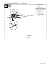
1 Strain Relief
2 Interconnecting Power Cord
. To ensure cord will be secure in
strain relief, slide supplied tub-
ing over cord.
Insert cord through strain relief.
. Ground lead must be wrapped
around ground current sensor
to protect ground wire against
damage from weld current.
3 Green Lead (Ground Lead)
4 Ground Current Sensor
5 Chassis Ground Stud
w/Hardware
Wrap ground lead 5 times around
ground current sensor. Connect
and secure end of ground lead to
chassis ground stud.
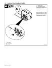
6 Terminal Block 1T
. For welding power sources re-
quiring dry contact closure,
move lead 38 at terminal block
to terminal D.
Refer to Sections 2-10 through 2-17
and make additional connections to
terminal block 1T according to the
applicable procedure.
Tools Needed:
1/4 in
3/8 in
1
4
2
5
3
6
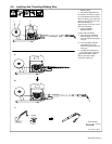
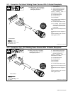
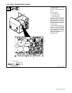
2-10. Connection For L-TEC Welding Power Sources With 7-Flat Socket Receptacle
Ref. 802 310 / Ref. 193 749
1 Terminal Block 1T
2 Interconnecting Power Cord
3 Green Lead (Connected To
Ground In Section 2-9)
Connect remaining leads to
terminal block as follows:
A: 115 VAC/Neutral Lead
B: 115 VAC/Hot Lead
C: No Connection
D: No Connection
E: 115 VAC/Contact Closure Lead
Secure strain relief clamp around
cord.
Reinstall and secure wrapper to
unit.
Connect remaining end of cord to
welding power source.
Tools Needed:
1/4 in
1
A
B
C
D
E
2
3
21
67
35
. Make ground lead connections
according to Section 2-9 before
following this procedure.