


OM-1579 Page 14
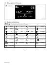
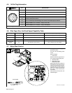
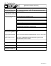
4-5. 14-Pin Plug Information
Pin* Pin Information
A 24 volts ac with respect to socket G.
B Contact closure to A completes 24 volts ac contactor control circuit.
AJ
G Circuit common for 24 volts AC circuit.
AJ
B
K
I
C +10 volts dc output to remote control with respect to socket D.
C
L
NH
D
M
G
D Remote control circuit common.
D
M
G
E
F
E 0 to +10 volts dc input command signal from remote control with respect to socket D.
H Voltage feedback; 0 to +10 volts dc, 1 volt per 10 arc volts.
F Current feedback; 0 to +10 volts dc, 1 volt per 100 amperes.
*The remaining pins are not used.
4-6. Wire Type, Size, And Feed Speed Capability Table
Motor Speed Wire Type Wire Size Feed Speed Capability
Standard All .023 To 5/64 in (0.6 To 2 mm) 50 To 780 ipm (1.3 To 19.8 mpm)
Standard All 3/32 To 7/64 in (2.4 To 2.8 mm) 50 To 700 ipm (1.3 To 17.8 mpm)
Standard All 1/8 in (3.2 mm) 50 To 300 ipm (1.3 To 7.6 mpm)
Optional High
Speed
All .023 To 5/64 in (0.6 To 2 mm) 92 To 1440 ipm (2.3 To 35.6 mpm)
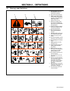
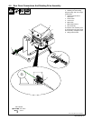
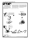
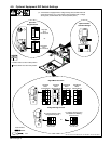
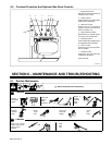
4-7. Motor Start Control
802 479 / Ref. 146 862-D
To change wire feed starting speed
proceed as follows:
Turn Off unit and welding power
source.
Remove wrapper.
1 Front Panel
Remove screw from upper left cor-
ner, and open hinged front panel.
2 Motor Board PC1
3 Motor Start Control
Potentiometer R70
Rotate potentiometer clockwise to
increase time it takes the motor to
ramp up to speed. Remove protec-
tive white rubber cap before making
adjustment. Adjust potentiometer
R70 using a small nonconductive
screwdriver.
Close and secure front panel, and
reinstall wrapper.
Tools Needed:
1/4 in
3
Non-Conductive
2
1