69-0895—1
2
C7189A WALL MOUNT TEMPERATURE SENSOR
5 Run cable to a hole at the selected wall location. Pull
approximately 3 inches of wire through the opening.
Color-coded, 18 gauge thermostat wire is recom-
mended.
NOTE: If the old thermostat has left marks on the wall
that are not covered by the C7189, order part no.
202689A Mounting Plate Accessory to mount
between the wall and the C7189.
RECYCLING NOTICE
If this control is replacing a control that contains
mercury in a sealed tube, do not place your old
control in the trash.
Contact your local waste management authority for
instructions regarding recycling and the proper
disposal of any control containing mercury in a
sealed tube.
If you have questions, call Honeywell Inc. at
1-800-468-1502, Monday through Friday, 7:00am
to 5:30pm.
Wiring
CAUTION
Keep wiring at least one foot away from large
inductive loads such as motors, line starters,
lightning ballasts, and large power distribution
panels. Failure to follow these wiring practices can
introduce electrical interference (noise), which can
cause erratic system operation. Use shielded cable
to reduce interference when rerouting is not
possible. Ground the shielded cable to the GND
terminal on the W8900.
Important
Erratic temperature readings from a sensor can
occur as a result of any of the wiring practices
described below. These practices must be
avoided to assure proper operation. Use shielded
cable to reduce interference if rerouting of sensor
wiring is not possible.
a. Do not route temperature sensor wiring with
building power wiring, next to control
contactors or near light dimming circuits,
electric motors or welding equipment.
b. Avoid poor wiring connections.
c. Avoid intermittent or missing building earth
ground.
CAUTION
Disconnect power supply before connecting to
wiring to prevent electrical shock or equipment
damage.
Wiring must comply with applicable codes, ordinances and
regulations.
1 Wire the C7189 Sensor to the W8900 Remote
Module terminals S1 and S. For an example of
general wiring of the C7189, see Fig. 2.
2 Push excess wire back into the hole. Plug the hole
using nonhardening caulk, putty or insulation to
prevent drafts from affecting performance.
3 Remove C7189 cover.
4 Mount the C7189 to the wall or junction box using
the screws and anchors provided.
5 Level the C7189 for appearance only. Device will
function properly even when not level.
6 Install C7189 cover.
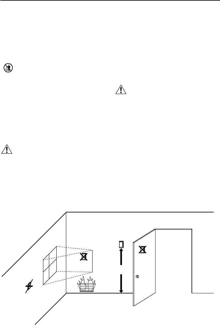
5 FEET
(1.5 METERS)
YES
NO
NO
NO
M4476
Fig. 1. Typical Location for C7189 Sensor.


