


C7600A SOLID STATE HUNIDITY SENSOR
3
63-2150—5
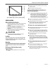
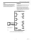
Fig. 2. C7600A output current vs. relative humidity.
INSTALLATION
When Installing this Product…
1. Read these instructions carefully. Failure to follow them
could damage the product or cause a hazardous
condition.
2. Check the ratings given on the product to make sure
the product is suitable for your application.
3. Installer must be a trained, experienced service
technician.
4. Checkout according to instructions provided with the
controller before leaving installation.
CAUTION
Disconnect power before installation to prevent
electrical shock or equipment damage.
Location
When selecting the location, make certain that the humidity
sensor is not exposed to rain, snow, or direct sunlight. The
C7600A Solid State Humidity Sensor is designed to operate
in 500 ft/min minimum airflow.
Mounting
The C7600A Solid State Humidity Sensor can be mounted in
any position; however, the sensor must be installed where it
is exposed to freely circulating air, with at least 500 ft/min
airflow.
Mounting the C7600 Solid State Humidity
Sensor Outdoors
³ Select a location protected from rain, snow or direct
sunlight.
HUMIDITY IN % RH
CURRENT IN mA
4
18
8
16
6
14
12
20
10
10
M3130
18.4
16.8
15.2
13.6
12.0
10.4
8.8
7.2
5.6
10
20
30
40
50
60
70
80
90
20 10090807060504030
RH (%) I (mA)
0
· Attach the sensor to the wall with two 1/8 in. (3 mm)
diameter screws.
» Wire as shown in the Wiring section.
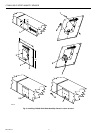
Installing C7600 Solid State Humidity Sensor in
Return Air Duct (See Fig. 3)
NOTE: Installers need to supply the following: sheet metal
cutter or snips; drill with 1/16 in. (2 mm), 1/8 in.
(3 mm) and 1/2 in. (13 mm) bits; screwdrivers; 1/2 in.
(13 mm) rubber grommet; eight self-tapping sheet
metal screws; and two 1/8 in. (3 mm) by 3/4 in.
(19 mm) machine screws with lockwashers and nuts.
³ Cut a 5 in. (127 mm) by 6 in. (152 mm) rectangular
hole in one side of the return air duct.
· Center the sensor on a 6 in. (152 mm) by 7 in. (178 mm)
piece of sheet metal. Mark locations for mounting
screws and for a hole for the control wire.
» Drill two 1/8 in. (3 mm) mounting holes for the sensor
and one 1/2 in. (13 mm) hole for the control wire.
¿ Drill eight starting holes in the sheet metal rectangle for
self-tapping sheet metal screws.
´ Center sheet metal rectangle over opening in duct so
there is a 1 in. (25 mm) overlap on all four sides. Then
mark the eight sheetmetal screw locations on the duct.
² Drill eight starting holes in the duct for self-tapping
sheet metal screws.
¶ Attach sensor to sheet metal rectangle with 1/8 in.
(3 mm) by 3/4 in. (19 mm) machine screws, washers
and nuts. Attach the machine screws from the outside
of the sheet metal to eliminate protrusions and possible
sharp edges.
º Place a rubber grommet in the 1/2 in. (13 mm) hole in
the sheet metal to protect the control wires from
abrasions.
¾ Put the control wires through the 1/2 in. (13 mm) hole
and wire as shown in the Wiring section.
µ Attach the sheet metal rectangle to the duct with self-
tapping sheet metal screws. Make sure that airflow over
the sensor is as shown in Fig. 3.