


T7047C,G,H REMOTE SPACE SENSORS
62-0179 4
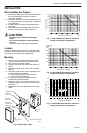
Fig. 6. T7047G1000 Remote Sensor resistance
change with change in temperature.
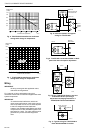
Fig. 7. T7047H1008 Remote Sensor resistance
change with change in temperature.
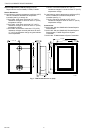
Wiring
IMPORTANT
All wiring must agree with applicable codes,
ordinances and regulations.
Fig. 8 through 16 show schematics and typical
connections. Also refer to instructions supplied with other
system components.
IMPORTANT
To avoid electrical interference, which can
cause erratic performance, keep wiring runs as
short as possible and do not run wires adjacent
to the line voltage electrical distribution
systems. Use shielded cable (Belden type 8762
or equivalent for 2-wire and Belden type 8772 or
equivalent for 3-wire). The cable shield must be
grounded only at the controlled equipment
case.
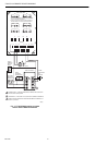
Fig. 8. Internal schematic and typical
wiring for T7047C1009.
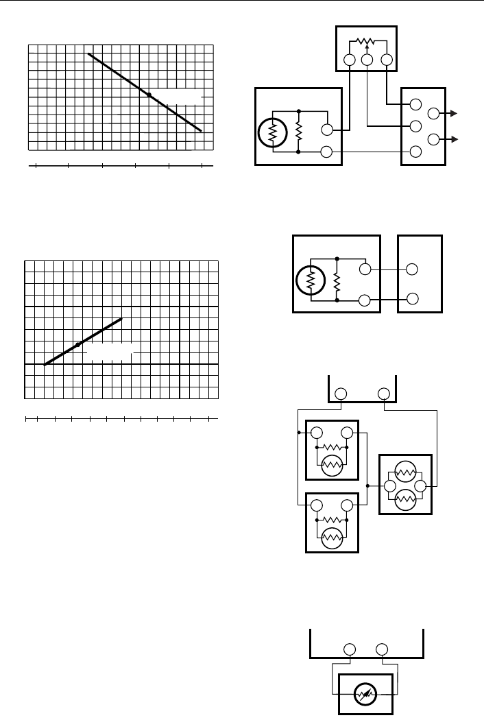
Fig. 9. T7047C1025 connected to W960 or W927
panel with internal setpoint adjustment.
Fig. 10. Two T7047C1025 Sensors and one
T7047G1000 Sensor providing a
temperature-averaging network for a
T7300/Q7300 Thermostat/Subbase.
Fig. 11. Typical wiring for T7047H1008 to
Excel 80/100/500/600 Controller.
1
000
9
00
8
00
7
00
6
00
5
00
10
20
30 40 50
60
70 80 90
100
R
ESISTANCE
(
OHMS)
710 OHMS AT
75 F (24 C)
TEMPERATURE (DEGREES)
M5354
-10
0 10
20 30 40
C
F
110
R
ESISTANCE
(
OHMS)
1
400
1317
1231
1145
1059
973
20 40
60
80 100 120
140 160
180 200 220
-7
0
10
20 30
40 50
60
70 80 90
100
F
C
1093 OHMS AT
75 F (24 C)
M1002
0
TEMPERATURE (DEGREES)
T1
T2
4
R
B
W
1
T1
T
T
M338
3
S963B1003
REMOTE SETPOINT
POTENTIOMETER
M7044 OR
M7045 MOTOR
TO 24V
POWE
R
SUPPL
Y
T7047C
t
T1
T2
T
T
M338
6
W960 OR
W927 PANEL
T7047C
t
M341
8
TT
Q7300
TT
T7047C
TT
T7047C
TT
T7047G1000
M1001
9
A1
A1
EXCEL 500/100/80
CONTROLLER
T7047H
COMMON