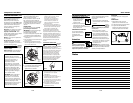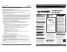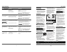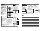
ASME SAFETY VALVE
Do not remove or
attempt to adjust
the safety valve!
This valve should be checked
occasionally by pulling the ring by hand.
Air may leak even after ring has been
released. However, if the leaking
continues for an extended period of
time, or if the safety valve is stuck and
cannot be activated by the ring, the
safety valve MUST be replaced. (Note:
Valve will reset when tank pressure
reaches 40-50 PSI.)
REGULATOR KNOB
1. This knob controls air pressure to an
air operated tool, or paint spray gun.
2. Turning knob clockwise increases air
pressure at outlet.
3. Turning counterclockwise will lower
air pressure at outlet.
4. Fully counterclockwise will shut off
flow of air completely.
OUTLET (TOOL) PRESSURE GAUGE
1. This gauge shows at-a-
glance, air pressure at
outlet. Air pressure is
measured in pounds per
square inch (psi).
2. Be sure this gauge reads ZERO before
changing air tools or disconnecting
hose from outlet.
TANK PRESSURE GAUGE
Gauge shows pressure in
tank indicating
compressor is building
pressure properly.
Disconnect power source
then release all pressure
from the system before
attempting to install,
service, relocate or perform any
maintenance.
!
WARNING
!
WARNING
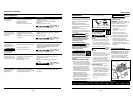
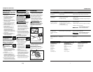
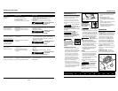
Funcionamiento
(Continuacíon)
permite verificar la presión de salida
muy fácilmente. Esta presión se mide
en barras.
2. Cerciórese de que el manómetro esté
en CERO antes de cambiar de
herramientas neumáticas o desconectar
la manguera.
MANOMETRO DEL TANQUE
Mide la presión del tanque
para verificar que el sistema
está funcionando
adecuadamente.
Mantenimiento
Desconecte el cordón eléctrico
del tomacorrientes y libere
toda la presión del sistema
antes de tratar de instalar, darle servicio,
cambiar de lugar o darle cualquier tipo de
mantenimiento.
!
ADVERTENCIA
21 Sp
Este compresor se debe chequear con
frecuencia para ver si tiene algún tipo de
problemas y le debe dar el siguiente
mantenimiento antes de cada uso.
1. Hále el anillo de la válvula de seguridad
y deje que calce en su posición normal.
Debe
reempla-
zar la válvula de seguridad si no la puede
activar o si hay fugas de aire una vez que
haya soltado el anillo.
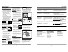
2. Coloque la unidad en posición
horizontal como indicado en la
Figura 8. Apague el compresor y libere
toda la presión, después: Abra la llave
de drenaje, ubicada debajo del tanque,
para drenarle toda la humedad.
3. APAGUE la unidad y limpie la tapa
del cabezal, el tanque y las líneas de
aire.
IMPORTANTE: Debe colocar el com-
presor lo más lejos posible del área de
trabajo, según lo permita la longitudud
de la manguera, para evitar que el filtro
se atasque.
!
ADVERTENCIA
LUBRICACION
Este compresor no requiere lubricación.
ALMACENAMIENTO
1. Mientras no lo esté usando debe
almacenar el compresor y las
mangueras en un sitio seco y frío.
2. Debe drenar el tanque.
3. Debe desconectar las mangueras y
colgarlas con los extremos hacia abajo
para que se drenen.
Serie FP2205
4
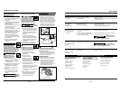
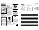
Operation (Cont.)
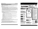
Handle - Designed to move the
compressor.
Tool Storage - 1/4 inch quick connect
couplers fit in holes to support air
chuck and other inflation fittings.
Never use the
handle on wheeled
units to lift the unit completely off the
ground.
Drain Petcock - This valve is located on
the bottom of the tank. Use this valve
to drain moisture from the tank daily
to reduce the risk of corrosion.
Reduce tank pressure below 10 PSI,
then drain moisture from tank daily to
avoid tank corrosion. Drain moisture
from tank(s) by opening the drain
petcock located underneath the tank.
LUBRICATION
This is an oilless product and DOES
NOT require lubrication to operate.
IMPORTANT: Do not operate compres-
sor before reading instructions or
damage may result.
1. Turn switch to OFF position and plug
in power cord.
!
WARNING
2. Attach hose to compressor outlet.
3. Attach chuck or other tool to open
end of hose.
4. Turn regulator clockwise to open air
flow.
5. Turn switch to ON position.
6. Compressor will build to maximum
preset pressure and shut off.
7. Adjust regulator to proper pressure
for tool or tire. Operate tool per
instructions. Compressor will
automatically restart when pressure
in tank drops below cut-in pressure.
8. Turn regulator knob counterclock-
wise to shut off the air and turn
switch to Off position.
In the ON position, the compressor
pumps air into the tank. It shuts off
automatically when unit reaches its
maximum preset pressure. In the OFF
position, the compressor will not
operate. This switch should be in the
OFF position when connecting or
disconnecting the power cord from the
electrical outlet.
MOISTURE IN COMPRESSED AIR
Moisture in compressed air will
form into droplets as it comes from
an air compressor pump. When
humidity is high or when a
compressor is in continuous use for
an extended period of time, this
moisture will collect in the tank.
When using a paint spray or
sandblast gun, this water will be
carried from the tank through the
hose, and out of the gun as
droplets mixed with the spray
material.
IMPORTANT: This condensation
will cause water spots in a paint
job, especially when spraying other
than water based paints. If
sandblasting, it will cause the sand
to cake and clog the gun,
rendering it ineffective. A filter in
the air line (MP3105), located as
near to the gun as possible, will
help eliminate this moisture.
Oilless Compressors
PSI
PSI
PSI
Notas
Figure 7
bar
Figure 5
Tank
Pressure
Regulator
On
Position
Safety
Valve
Tool
Pressure
Figure 6
Off
Position
Figure 8


