


3
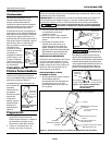
Spray Gun Set-up
The pressure for atomization is con-
trolled at the air source. The amount of
fluid is adjusted by the fluid control
knob, the paint viscosity and the air
pressure.
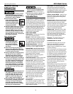
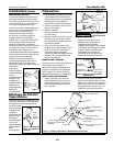
The gravity feed cup screws onto the top
of the gun body creating a positive fluid
pressure in the nozzle (See Figure 2).
Preparation
1. Thoroughly mix and thin paint in
accordance with the paint manufac-
turer’s instructions. Most materials
will spray readily if thinned properly.
2 Strain material through cheese
cloth or a paint strainer.
3. Fill the canister about 3/4 full and
start the air compressor.
4. Set up a piece of cardboard or other
scrap material to use as a target and
adjust for best spray pattern.
5. Test the consistency of the material
by making a few strokes on a card-
board target. If material still appears
too thick, add a small amount of
thinner. THIN WITH CARE!! Do not
exceed paint manufactuer’s thinning
recommendations.
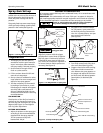
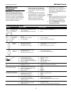
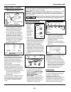
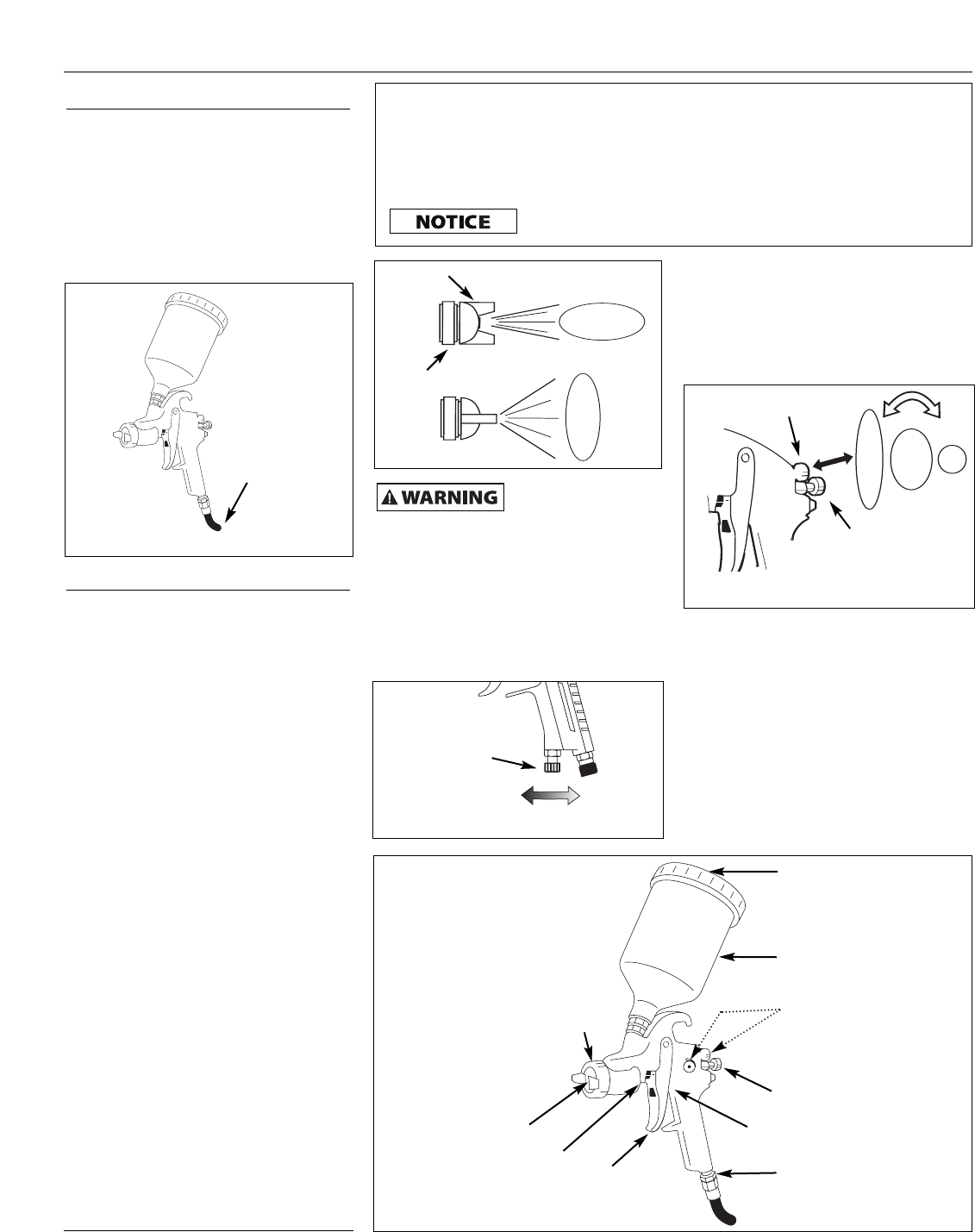
FAN DIRECTION
The direction of the fan (horizontal or
vertical) can be changed by loosening
the lock ring and turning the air cap 90
degrees (See Figure 3). Hand tighten
lock ring after adjustment.
PATTERN ADJUSTMENT
1. Adjust air pressure to the spray gun
according to the recommendations
supplied with the spray material.
This air pressure usually falls
between 40 - 60 psi.
Do not exceed
spray gun maxi-
mum pressure.
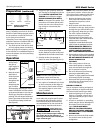
Adjust air pressure with the trigger
pulled and air control knob (if applica-
ble) fully open. If reduced air pressure
is desired for some areas of the spray
job, use the air compressor regulator or
air control knob to reduce pressure as
necessary (See Figure 4).
2. Set pattern size to desired shape.
For full pattern, open pattern con-
trol knob by turning counterclock-
wise. For a round pattern, turn pat-
tern control knob clockwise
(See Figure 6).
3. Turn fluid control knob fully clock-
wise until closed (See Figure 6).
4. Trigger a short burst while turning
fluid control knob counterclock-
wise. Observe the spray pattern on
the target and adjust the fluid con-
trol knob until the desired pattern
(atomization) is obtained (See
Figure 7).
WATER/OIL IN COMPRESSED AIR
All compressor pumps discharge some condensed water, oil or contaminates with
the compressed air.
IMPORTANT: This condensation will cause “fish eyes” to appear in the paint
job. Install appropriate water/oil removal equipment and controls as necessary
for the intended application. Locate filter as close to spray gun as possible.
Failure to install appropriate water/oil removal equipment
may result in damage to machinery or workpiece.
Operating Instructions HDS Model Series
Figure 3
Horizontal Fan
Vertical Fan
Air Cap
Lock Ring
Figure 4 - Air Adjustment on Spray Gun
Increase
Air Flow
Decrease
Air Flow
Air Control
Knob
Figure 6 - Pattern Size
Pattern control knob
Fluid control
knob
Figure 5 - Gravity Feed Spray Gun
Vent Hole
Fluid Control Knob
Trigger
Fluid Tip (Nozzle)
Pattern Control Knob
(location depends on
model)
Cup
Air Cap
1/4 in. NPS Air Inlet Fitting
Fluid Packing Nut
Air Valve Packing Nut
Figure 2 - Gravity Feed Cup Set-up
Filtered,
Regulated
Air Source