2
EVERY MACHINE IS THOROUGHLY TESTED BEFORE LEAVING THE FACTORY. EACH MACHINE IS SUPPLIED
WITH A COPY OF THIS MANUAL. OPERATORS OF THIS EQUIPMENT MUST READ AND BE FAMILIAR WITH THE
SAFETY WARNINGS. FAILURE TO OBEY WARNINGS MAY RESULT IN INJURY OR DEATH. FOLLOW
INSTRUCTIONS STRICTLY TO ENSURE LONG SERVICE IN NORMAL OPERATION.
CONTENTS
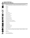
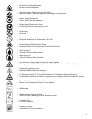
Symbol Definitions .................................................................................................................................4 - 6
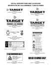
Decal Descriptions and Locations .........................................................................................................7
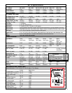
Saw Configurations and Models / Power Source / Dimensions............................................................9
Safety Warnings - DO's & DO NOT's ....................................................................................................10 - 11
Reference Figures .................................................................................................................................12
Pre-Operation Checklist / Maintenance Schedule ................................................................................13
Instructions:
1. Features .................................................................................................................................14
2. Assembly ................................................................................................................................14
3. General Instructions ...............................................................................................................14
4. Check Before Starting ............................................................................................................15
5. Fitting the Blade......................................................................................................................15
6. Starting the Power Source......................................................................................................15
7. Maneuver the Saw..................................................................................................................16
8. To Start Sawing.......................................................................................................................16
9. Stopping the Saw....................................................................................................................16
10. Maintenance Instructions .......................................................................................................17
11. Optional And Accessory (Field Installed)................................................................................17
12. Governor Speed .....................................................................................................................18
13. Repairs ...................................................................................................................................18
14. Service Parts ..........................................................................................................................18
Parts List Diagrams:
Diagram 1 - Frame & Axle .....................................................................................................................20, 21
Diagram 2 - Depth Control (Screw Feed)..............................................................................................22, 23
Diagram 3 - Depth Control (Lock Bar)...................................................................................................24, 25
Diagram 4 - Pointer & Belt Guard..........................................................................................................26, 27
Diagram 5 - Guards & Water Distribution .............................................................................................28, 29
Diagram 6 - Blade Guard.......................................................................................................................30, 31
Diagram 7 - Engine & Bladeshaft ..........................................................................................................32, 33
Diagram 8 - Electric Motor.....................................................................................................................34, 35
Diagram 9 - Air Motor ............................................................................................................................36, 37
Diagram 10 - Kit, Water Tank (174957).................................................................................................38


