


21
SERVICE AND ADJUSTMENTS
E
A
M
Q
F
B
C
C
O
H
D
D
P
Fig. 25
Fig. 26
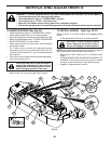
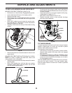
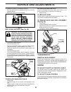
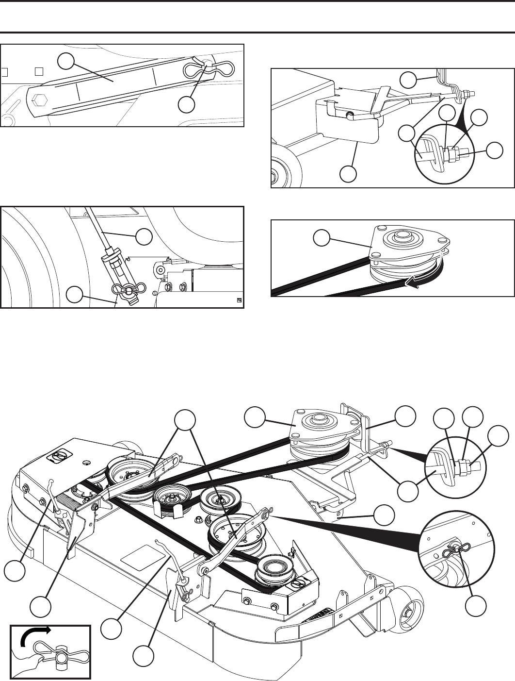
• Install belt onto electric clutch pulley (M).
Fig. 23
Fig. 24
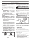
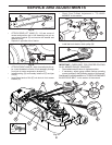
• ATTACH REAR LIFT LINKS (C) - Lift rear corner of
mower and position slot in link assembly over pin on
rear mower bracket (D) and secure with washer and
retainer spring.
• Repeat on opposite side of tractor.
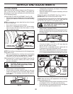
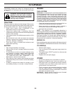
• ATTACH FRONT LINK (E) - Work from left side of trac-
tor. Insert threaded rod end of link assembly through
front hole in tractor suspension bracket (F).
• Install bushing (O) and loosely install nut (P) and jam
nut (Q).
• Insert flared ends of link (E) into slots in front mower
bracket (H).
E
P
F
Q
H
O
M
A
B
IMPORTANT: CHECK BELT FOR PROPER ROUTING
IN ALL MOWER PULLEY GROOVES.
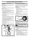
• Raise attachment lift lever to highest position.
• If necessary, adjust gauge wheels before op er at ing
mower as shown in the Operation section of this manual.
See Mower Drive Belt Installation in "TO REPLACE MOWER
BLADE DRIVE BELT" in this section of the manual.
• Check Front-To-Back Adjustment in "TO LEVEL
MOWER" in this section.
D
C
Fig. 27