


5
English
PRIOR TO OPERATION
1. Power source
Ensure that the power source to be utilized conforms
to the power requirements specified on the product
nameplate.
2. Power switch
Ensure that the power switch is in the OFF position. If
the plug is connected to a power receptacle while the
power switch is in the ON position, the power tool
will start operating immediately, which could cause a
serious accident.
3. Extension cord
When the work area is removed from the power
source, use an extension cord of sufficient thickness
and rated capacity. The extension cord should be
kept as short as practicable.
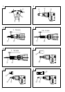
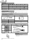
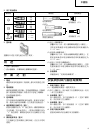
4. Confirm the direction of bit rotation (Fig. 1)
The bit rotates clockwise (viewed from the rear side)
when the reversing switch lever is set to the “R” side
position. When the lever is set to the “L” side position,
the bit rotates counterclockwise and can be used to
loosen and remove screws.
5. Adjusting the tightening depth (Fig. 2)
The tightening depth can be adjusted by turning
locator right and left click feeling.
(1) For hex-head screws:
Mount a hex-head screw on the hex-socket and set
the distance between the sub-stopper end and the
screw head neck to 1–1.5 mm, as shown in Fig. 3.
(2) For drywall screws:
Mount a drywall screw on the bit, and set the distance
between the sub-stopper end and the screw head to
1.5–2 mm, as shown in Fig. 4.
(3) For cross-recessed self-drilling screws:
Mount a self-drilling screw on the bit, and set the
distance between the sub-stopper end and the screw
head bottom to 1–1.5 mm, as shown in Fig. 5.
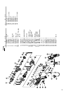
6. Mounting the bit
For details, refer to the item “Mounting and
dismounting the bit”.
MOUNTING AND DISMOUNTING THE HEX-
SOCKET OR THE BIT
1. Dismounting the hex-socket (Fig. 6)
(1) While rotating the Sub-Stopper pull it out from the
locator.
(2) Remove the hex-socket, hold it with the opposite
side of bit by hand or vise and pull out the bit with
pliers.
2. Dismounting the bit (Fig. 7)
Remove sub-stopper (G) as the same manner of hex-
head socket and remove the bit holder, then pull out
the bit with pliers.
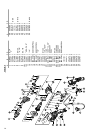
3. Dismounting the bit (Fig. 8)
Remove the sub-stopper (F) as the same manner of
hex-head socket and remove the bit holder, then pull
out the bit with pliers.
4. Mounting the hex-socket or the bit
Install the bit in the reverse order to removal.
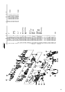
HOW TO USE THE SCREW DRIVER
1. Switch operation and rotational speed adjustment
Bit rotational speed can be adjusted between 0 –
6000/min (W6VM) or 0 – 4500/min (W6V4) or
0 – 3000/min (W6VA4) or 0 – 2600/min (W6VB3) or 0 –
1700/min (W8VB2) varying the degree by which the
trigger switch is pulled. Rotational speed increases
as the trigger switch is pulled, and reaches a
maximum speed of 6000/min (W6VM) or 4500
/min (W6V4) or 3000/min (W6VA4) or 2600
/min (W6VB3) or 1700/min (W8VB2) when the trigger
switch is pulled fully.
To facilitate continuous operation, pull the trigger
switch and depress the switch stopper. The switch
will then remain ON even when the finger is released.
By pulling the trigger switch again, the switch stopper
disengages and the switch is turned OFF when the
trigger switch is released.
2. Screw Driver operation
When the switch is turned ON, the motor starts to run
but the hex-socket (or the bit) does not rotate. Attach
the hex-socket to the screw head groove, and push
the Screw Driver against the screw. The hex-socket
then rotates and tightens the screw.
CAUTION
Ensure that the Screw Driver is held truly
perpendicular to the head of the screw.
If held at an angle, the driving force will not be fully
transferred to the screw, and the screw head and/or
hex-socket will be damaged. Hex-socket rotation stops
when pushing force is released.
3. Direction of hex-socket rotation
The hex-socket rotates clockwise (viewed from the
rear side) when the reversing switch lever is set to
the “R” side position. When the lever is set to the “L”
side position, the hex-socket rotates counter-
clockwise, and can be used to loosen and remove
screws.
CAUTION
Never change the direction of hex-socket (or bit
holder) rotation while the motor is running. To do so
would seriously damage the motor. Turn the power
switch OFF before changing the direction of hex-
socket (or bit holder) rotation.
MAINTENANCE AND INSPECTION
1. Inspecting the hex-socket (or bit)
Since continued use of a worn hex-socket (bit) will
damage screw heads, replace the hexsocket (bit) with
a new one as soon as excessive wear is noticed.
2. Inspecting the mounting screws
Regularly inspect all mounting screws and ensure
that they are properly tightened. Should any of the
screws be loose, retighten them immediately. Failure
to do so could result in serious hazard.
3. Maintenance of the motor
The motor unit winding is the very ”heart” of the
power tool. Exercise due care to ensure the winding
does not become damaged and/or wet with oil or
water.