


16607103_ed5 21
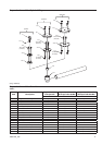
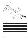
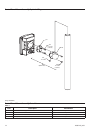
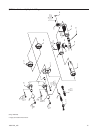
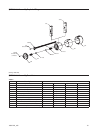
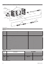
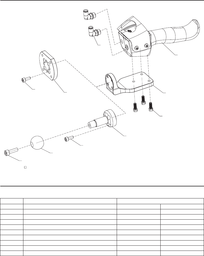
QMM Pneumatic Handle with Flange Exploded Diagram
381
382
383
16-20 Nm
(3 Places)
314
4
317
384
4
315
116
30-35 Nm
12-16 Nm
(4 Places)
12-16 Nm
(4 Places)
(Dwg. 16608911)
□ Apply Serviceable Thread Locker
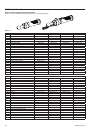
QMM Pneumatic Handle with Flange Parts List
Table-11
Item Description Part Number
* Pneumatic Handle Assembly QMMH-A35 QMMH-A36
4 Cap Head Screw (M6 x 1 x 16) QMM-F1-638 QMM-F1-638
116 Cap Head Screw (M8 x 1.25 x 25) QMM-T6-638 ---
314 Bracket QMMH-900-D ---
315 End Ball QMMH-629 ---
317 Handle Flat Mount Flange --- QMMH-35
381 Pendant Handle 80148539 80148539
382 Pneumatic Handle Bracket QMMH-35A QMMH-35A
383 Cap Head Screw (1/4-20 x 5/8) QMMH-35-638 QMMH-35-638
384 Male Stud Elbow, 1/4-18 NPT QMMH-188 QMMH-188