


2
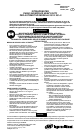
WARNING LABEL IDENTIFICATION
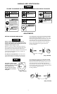
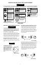
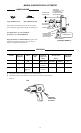
FAILURE TO OBSERVE THE FOLLOWING WARNINGS COULD RESULT IN INJURY.
Always wear eye protection
when operating or perform-
ing maintenance on this tool.
WARNING
WARNING
Always wear hearing
protection when operating
this tool.
Always turn off the air sup-
ply and disconnect the air
supply hose before instal-
ling, removing or adjusting
any accessory on this tool,
or before performing any
maintenance on this tool.
WARNING
Air powered tools can vibrate
in use. Vibration, repetitive
motions or uncomfortable
positions may be harmful to
your hands and arms. Stop
using any tool if discomfort,
tingling feeling or pain occurs.
Seek medical advice before re-
suming use.
WARNING
Do not carry the tool by the
hose.
WARNING
WARNING
Do not use damaged, frayed
or deteriorated air hoses
and fittings.
WARNING
Keep body stance balanced
and firm. Do not overreach
when operating this tool.
WARNING
Operate at 90 psig (6.2 bar/
620 kPa) Maximum air pres-
sure.
90 psig
(6.2bar/620kPa)
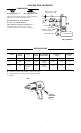
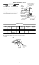
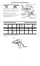
ADJUSTMENTS
SETTING THE POWER REGULATOR
Impact wrenches are not torque control devices.
Fasteners with specific torque requirements must be
checked with suitable torque measuring devices after
installation with an impact wrench.
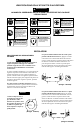
Models 231 and 231--2 Impact Wrenches incorporate a
power regulator into the reverse mechanism that allows
the operator to have either full power output in one
direction and reduced power output in t he other direction
or full power output in both directions. To adjust the
power, proceed as follows:
For full power in both directions, rotate the reve rse
valve until the notch on each end of the reverse valve
aligns with the number 5 on each side of the housing.
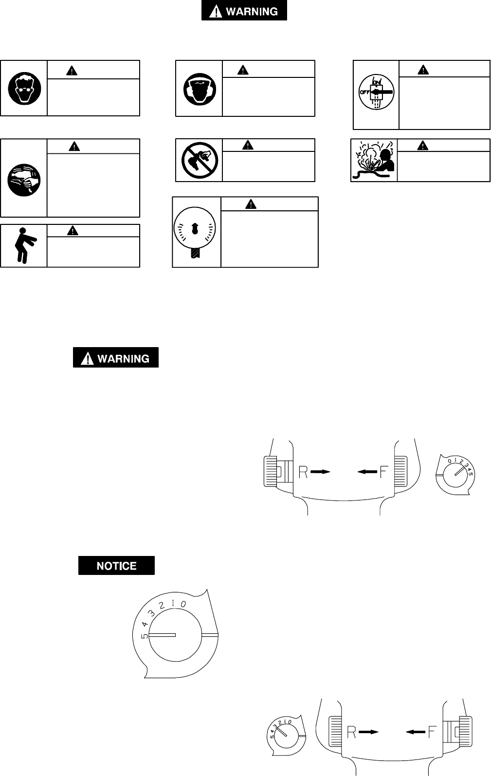
The numbers 0 thru 5 on the
housing are only for reference
and DO NOT denote a specific
power output. Zero (0)
designates the lowest power
output while five (5) denotes
the highest.
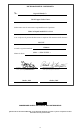
For reduced power in the forward direction and full
power in the reverse direction, push the reverse valve
inward on the right side of the tool and rotate the reverse
valve until the notch on the right side aligns with the
desired number on the right side. Thi s provides reduced
power in forward but full power in reverse when the
reverse valve is pushed in the opposite direction.
See Dwg. TPD1248.
(Dwg. TPD1248)
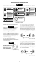
For reduced power in the reverse direction and full
power in the forward direction, push the reverse valve
inward on the left side of the tool and rotate the reverse
valve until the notch on the left side aligns with the
desired number on the left side. This provides full power
in forward but re duced power in reverse when the reverse
valve is pushed the opposite direction.
See Dwg. TPD1249.
(Dwg. TPD1247)
(Dwg. TPD1249)