


EN-2 04584827_ed2
EN
Installation and Lubrication
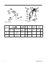
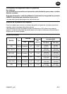
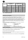
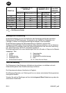
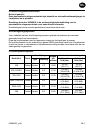
Size air supply line to ensure tool's maximum operating pressure (PMAX) at tool inlet.
Drain condensate from valve(s) at low point(s) of piping, air filter and compressor tank daily.
Install a properly sized Safety Air Fuse upstream of hose and use an anti-whip device
across any hose coupling without internal shut-off, to prevent hose whipping if a hose fails
or coupling disconnects. See drawing 16573172 and table on page 2. Maintenance
frequency is shown in circular arrow and defined as h=hours, d=days, and m=months.
Items identified as:
Parts and Maintenance
When the life of the tool has expired, it is recommended that the tool be disassembled,
degreased and parts be separated by material so that they can be recycled.
The original language of this manual is English.
Tool repair and maintenance should only be carried out by an authorized Service Center.
Refer all communications to the nearest IngersollRand Office or Distributor.
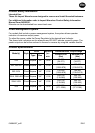
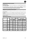
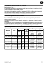
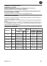
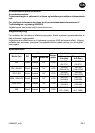
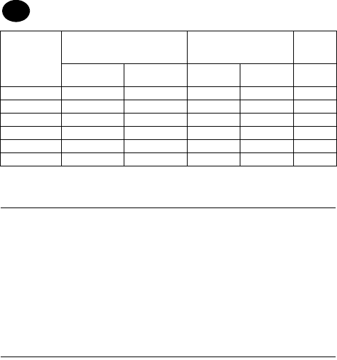
Model(s)
Sound Level dB (A)
(ISO15744)
Sound Level dB (A)
(ANSI S5.1-1971)
Vibration
Level
(ISO8662)
† Pressure (L
p
) ‡ Power (L
w
)
Pressure
Power
(ISO3744)
m/s²
235 --- --- 90.7 103.7 3.8
252, 252-EU 89.7 100.7 --- --- 3.0
252-3-EU 89.7 100.7 --- --- 3.0
255A, 255A-EU --- --- 93.7 106.7 4.6
255A-3-EU --- --- 93.7 106.7 4.0
258 --- --- 96.6 109.6 3.4
† K
pA
= 3dB measurement uncertanity
‡ K
wA
= 3dB measurement uncertanity
1. Air filter 6. Thread size
2. Regulator 7. Coupling
3. Lubricator 8. Safety Air Fuse
4. Emergency shut-off valve 9. Oil
5. Hose diameter 10. Oil - Fill the Chamber