


2 10569408_ed1
WARNING
Always wear eye protection when operating or performing maintenance on this tool.
Always turn off the air supply and disconnect the air supply hose before installing, removing or adjusting any accessory on this tool, or before
performing any maintenance on this tool.
Note: When reading the instructions, refer to exploded diagrams in Parts Information Manuals when applicable (see under Related Documentation for form
numbers).
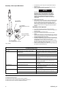
Lubrication
Each time a Series 3940, 3942 or 3955 Impactool is disassembled for
maintenance and repair or replacement of parts, lubricate the tool as
follows:
1. Work approximately 12 to 15 cc of Ingersoll-Rand No. 170 Grease
into the impact mechanism. Coat the Anvil (38) lightly with grease.
Also, coat the inside of the Hammer Case Bushing (40) with grease.
Inject approximately 2 to 4 cc of grease into the Grease Fitting (2).
2. Use Ingersoll-Rand No. 10 Oil for lubricating the motor. Inject
approximately 1 to 2 cc of oil into the Straight Inlet (10) before
attaching the air hose.
Disassembly
General Instructions
1. Do not disassemble the tool any further than necessary to replace or
repair damaged parts.
2. Whenever grasping a tool or a part in a vise, always use leather-
covered or copper-covered vise jaws to protect the surface of the
part and help prevent distortion. This is particularly true of threaded
members and housings.
3. Do not remove any part which is a press fit in or on a subassembly
unless the removal of that part is necessary for repairs or
replacement.
4. Do not disassemble the tool unless you have a complete set of new
gaskets and O-rings for replacement.
Disassembly of the Impactool
1. Grasp tool in copper-covered or leather-covered vise jaws with
square drive upward.
2. Squeeze sides of the Exhaust Deflector (32) and remove from Motor
Housing Assembly (26). Remove the Exhaust Silencer (33).
3. Using a hex wrench, unscrew and remove the four Hammer Case
Cap Screws (41) and remove Dead Handle Bracket (42).
4. While lightly tapping on the end of Anvil (38) with a plastic hammer,
lift off Hammer Case (39).
5. Remove the Hammer Case Gasket (34).
6. Remove Anvil by rotating it as it is lifted out of the assembly.
7. Lift remaining hammer assembly off rotor shaft.
8. Push two Hammer Pins (36) out of the Hammer Frame
Assembly (35) and slide two Hammers (37) out of the Frame.
Disassembly of the Impact Mechanism
1. Set mechanism, driver end up, on a workbench.
NOTICE
Note the twin hammers within the Hammer Frame.
These are identical, but must be placed in the Hammer
Frame in a certain relationship. Using a felt-tipped pen,
mark the top hammer “T↑” and the bottom hammer
“B↑” with the arrows pointing upward. Mark both
Hammers on the same end.
2. With mechanism sitting upright on a workbench, slowly rotate Anvil in
a clockwise direction until it comes up solid.
NOTICE
If you continue to rotate the Anvil, it will cam the
Hammers out of engagement. Do not allow this to
happen; merely rotate the Anvil until it comes up solid.
3. Hold Hammer Frame firmly and, without disturbing hammers, gently
lift Anvil, simultaneously rotating it clockwise about 1/8 of a turn, from
the Hammer Frame.
NOTICE
The twin hammers will be free to slide from the Hammer
Frame when the Hammer Pins are removed. Do not drop
the Hammers.
4. With Anvil removed, lift out the two Hammer Pins.
5. Remove the Hammers.
Disassembly of the Reverse Valve
1. Lightly clamp Motor Housing Assembly (26) in leather-covered or
copper-covered vise jaws with Handle Assembly (1) upward.
NOTICE
Excessive clamping pressure will distort the Motor
Housing and make motor removal extremely difficult. Do
not insert the hammer case end of the Motor Housing
more than 1” (25 mm) into the vise jaws.
2. Using a hex wrench, unscrew and remove the four Handle Cap
Screws (15). Lift assembled handle and Handle Gasket (17) off
Motor Housing and set them aside.
3. Lift Motor Clamp Washer(s) (16) off Housing.
4. Move Reverse Lever (12) to center position and using a drift pin to
push from below, grasp Lever and lift Reverse Valve Assembly (13)
out of Housing.
NOTICE
Make certain the Lever is in the center position to avoid
jamming the Reverse Lock Plunger (30) when the
Reverse Valve Assembly is removed.
5. Pull Lever off Reverse Valve and remove Reverse Valve Bushing
Seal (14) from groove on Valve.
6. Using needle nose pliers, remove Reverse Lock Plunger and
Reverse Lock Plunger Spring (31) from Motor Housing.
Disassembly of the Motor
1. Remove assembled motor and Motor Housing from vise jaws and
using a plastic hammer, tap splined shaft of Rotor (22) to dislodge
Rotor from Front Rotor Bearing (25).
2. Lift Motor Housing (26) off Rotor, Rear End Plate (20) and Rear Rotor
Bearing (18) which will remain together as a unit.
3. Remove Vanes (23) from Rotor.
4. Pull Rear End Plate off Rotor.
5. Open a set of vise jaws wide enough to clear hub of Rear End Plate
and sharply rap hub end of end plate on top of jaws to dislodge Rear
Rotor Bearing.
6. Remove Cylinder Dowel (19).
7. For 3940 and 3942 Series: To remove Cylinder (21) and Front End
Plate (24), thread four 1/4”-20 thread socket head cap screws that
are at least 3” (75 mm) long into handle end of Housing. Grasping
Housing with installed screws downward, sharply strike heads of
screws on a sturdy table to dislodge Cylinder. Cylinder should drop
out of Housing after a few impacts. If it does not, proceed as follows:
For 3955 Series: To remove Cylinder (21) and Front End Plate (24),
thread four 5/16”-18 thread socket head cap screws that are at least
3” (75 mm) long into handle end of Housing. Grasping Housing with
installed screws downward, sharply strike heads of screws on a
sturdy table to dislodge Cylinder. Cylinder should drop out of Housing
after a few impacts. If it does not, proceed as follows: