


636103PAGE2OF4
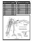
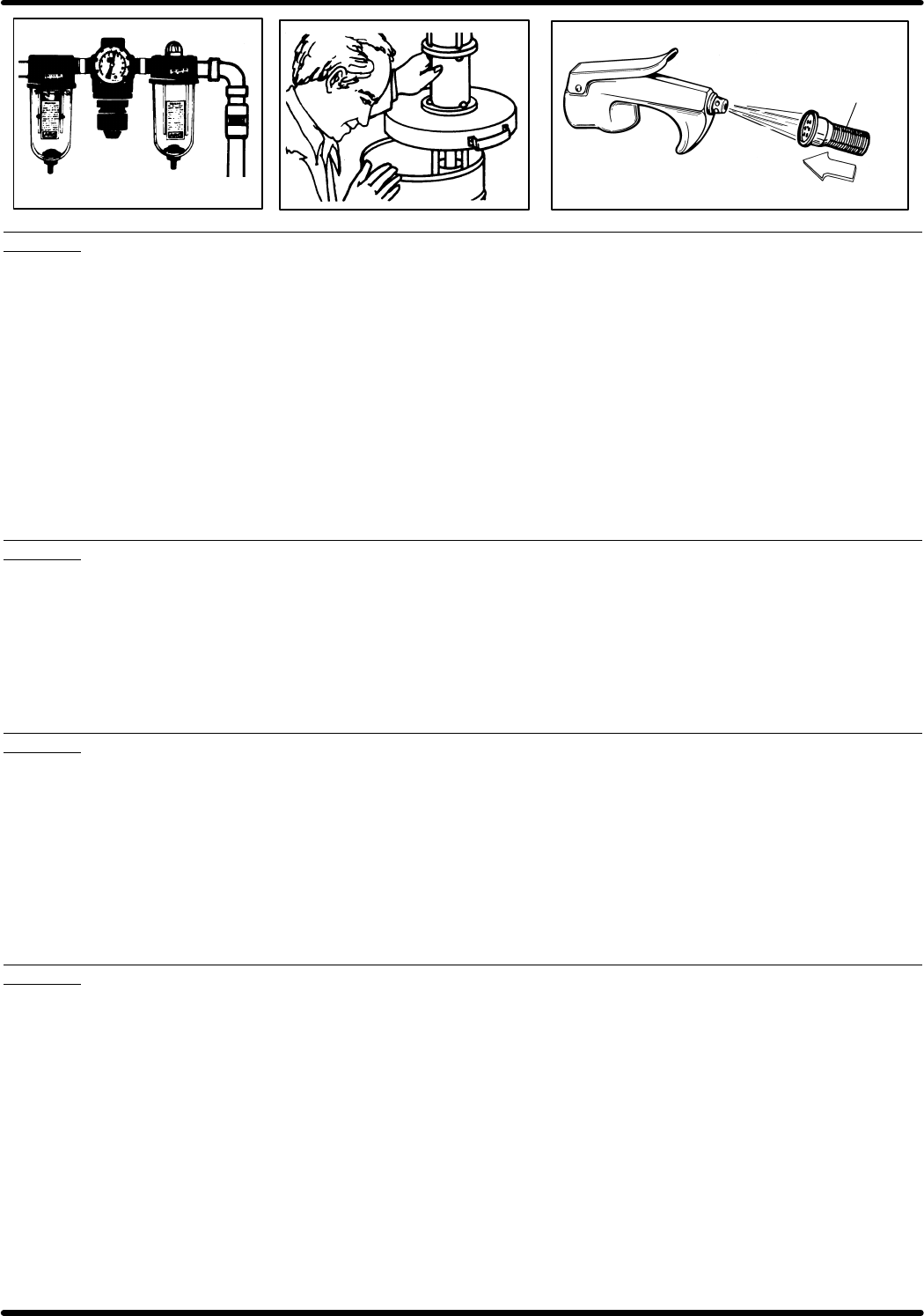
Direction oflubricant flow.
Filter (disc type or screen type)
A
B
C
17
SECTION 1
If little or no lubricant can be obtained from the control handle:
A. Check air lineconnection to pump tomake certain there isair presĆ
sure to the pump.
B. Check lubricant container to make certain lubricant is not exĆ
hausted.
C. If above conditions areokay and no lubricantcan be obtained from the
control handle, clean the filter in the bottom of the control handle.
1. Disconnect or shut off the air supply to the pump.
2. Pull (14) handle onthe control handle torelieve pressure in theline
from pump to the control handle.
3. Remove control handle from swivelslowly. If filter is plugged, there
can still be some pressure retained in the line. Remove the control
handle slowly to allow pressure to bleed off slowly so thatno injury
can be caused by grease injection.
4. Remove (16) adapter from control handle.
5. Remove (18) spring and (17) filter.
a. Clean exterior of filterin a solvent with abrush to remove mostof
the foreign material and lubricant from the outside of the filter.
b. Blow air through thefilter inthe oposite directionof lubricant flow.
CAUTION: Be sure to wear eye protection, goggles or glasses
when doing this.
c. Repeat directions a" and b" until filter is clean.
6. If filter is damaged, replace it. (Deformed discs on old style filter or
broken screen on new style filter which would allow dirt to pass on
thru the filter).
7. Reassemble control handle and then assemble to swivel.
SECTION 2
If lubricant leaks excessively around top of (5) piston:
A. Replace the two (26) packings. Also replace (5) piston if it is badly
scored on area that packing seals.
1. Follow instruction 1,2 and 3 as described in Section 1.
2. Remove the (1) nut and (2) pin that holds the two (28) links to the
(27) head.Thiswill allowthe(14)handle tobemovedout oftheway
from the (5) piston.
3. Place the flats of the (15) body in a vice.
4. Use an endwrench orcrescent wrench onthe flats ofthe (27) head
and remove the head from the (15) body.
5. Remove (25) spring and (23) spring from the (27) head.
6. Remove the (5) piston by pulling it out of the top of the (27) head.
7. Remove the (25) washerand two (26)packings from the(27)head.
8. Install two new (26) packings and (25) washer in the (27) head.
9. Reassemble the control handle in the reverse sequence of disasĆ
sembly steps 6, 5, 4.
SECTION 3
If control handle will not develop additional pressure:
A. If dirt got bythe (17) filter inthe bottomof the controlhandle, the(9)
outlet checkmay be fouledor the (19) ballsin the(15) body maybe
fouled.
1. Follow instruction 1,2 and 3 as described in Section 1.
2. Remove (8) valve body from (10) body.
3. Remove (11) retainer, (12) spring and (13) ball.
4. Clean ball seat of (10) body and (13) ball.
5. Examine ball seat of (10) body and (13) ball for nicks or score
marks. Replace damaged parts.
6. Remove (27) head from (15) body.
7. Remove (22) valve seat,two (19) balls, two(20) ball stops and(21)
spring from (15) body.
8. Clean ballseat in(15) body,ball seatin (22)valveseat andtwo (19)
balls.
9. Examine ball seats and balls for nicks or score marks. Replace
damaged parts.
10. Reassemble in the reverse sequence steps 8,7,6,5,3,2. See drawĆ
ing of control handle for correct placement of parts.
SECTION 4
If 636028 HydraulicCoupler locks ontothe greasefitting andcannot be
removed:
A. Unscrewthe (6)needle onetotwo turns.Thiswill relievethegrease
pressure out of the bleed hole beside the (6) needle.
B. Remove control handle from the greasefitting and retighten the (6)
needle.