


PAGE2OF4
650556Ć1
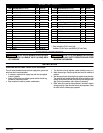
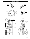
PARTS LIST / 650556-1
ITEM DESCRIPTION(Size in Inches)
QTY
PART NO. ITEM DESCRIPTION(Size In Inches)
QTY
PART NO.
1 TwoBall PistonPump (1) 650685ĆP43
2 CartAssembly (IncludesItems 3thru14) (1) 67139
3 Cotter Pin (3/32") (2) Y15Ć35ĆC
4 Washer (4) 91522
5 Tip (2) 91011
6 Washer(3/8") (6) Y13Ć6ĆC
7 Screw(3/8"Ć 16x1Ć1/4") (4) Y6Ć66ĆC
8 Nut(3/8" Ć16) (4) Y12Ć6ĆC
9 WheelAssembly (2) 91515
10 Brace (1) 95102
11 Screw(5/16"Ć 18x3/4") (4) Y6Ć53ĆC
12 Nut(5/16" Ć18) (4) Y12Ć5ĆC
13 Washer(5/16") (4) Y14Ć516ĆC
14 Cart Welding Assembly (1) 67138
15 MaterialFilter (IncludesItem 16) (1) 651422Ć70
16 Plug(3/8") (1) Y17Ć13ĆS
17 Muffler (1) 91790ĆZZ
j 18 3/4" SuctionHoseAssembly (1) 622606Ć5
j 19 90_ Elbow(3/4") (1) Y43Ć15ĆS
j 20 Suction Tube (5Gallon) (1) 94263Ć1
21 HoseAssembly (1) 628092ĆF
22 Gauge (1) 100067
23 ModularPiggybackFilter/Regulator (1) P29241Ć100
24 Nipple(1/2"x 1Ć1/2"(m)) (1) Y27Ć54ĆC
25 Bushing(1/2" Ć14(m) x1/4"Ć 18(f)) (1) 94271
26 Nipple(1/4"Ć 18(m)) (2) 1950
27 StreetTee(1/4"Ć 18) (1) 94270
28 NeedleValve (1) 94269
29 Adapter(1" (m)x1/2" (f)) (1) 94256
30 90_ Adapter(1"(m) x1/4"(f) x3/4"(f)) (1) 94254
31 Plug (1) Y17Ć11ĆS
jParts included in 67140Ć1 Asm (std)
Available: 67140Ć2 Asm. uses 94263Ć2 (36" Inlet Tube)
OPERATING INSTRUCTIONS
WARNING
DO NOT EXCEEDMAXIMUM OPERATING PRESĆ
SURE OF 6000 P.S.I. (414 BAR) AT 100 P.S.I. (6.9 BAR) AIR INĆ
LET PRESSURE.
WARNING
REFER TO THE PUMP MANUAL FORADDITIONĆ
AL OPERATING AND SAFETY PRECAUTIONS AND OTHER
IMPORTANT INFORMATION.
INSTALLATION
OPERATING INSTRUCTIONS / INITIAL SETUP PROCEDURE
This unit comesassembled exceptforthe airsupply hose,gunand maĆ
terial hose which must be attached.
• A connector, coupler and air supply hose and must be supplied
to the air regulator.
• Attach a Ground wire to a suitable ground and the Ground Lug
provided on the pump Air Motor.
• Keep containers covered to prevent contamination.
1. Turn the knob on the air regulator counterĆclockwise to zero p.s.i.
2. Attach hose and gun. Place pump inlet tube into a full container of
material.
3. Start the pump to cycle by turning the airregulator knob clockwise.
The pump will cycle several strokes until pressure is built up in the
system, atwhich timeitwill stall,checkfor anyloosefittings orleakĆ
age. Check all connections and reĆtighten as necessary.
4. Relief Valve (28) is used to relieve pressure in the hose in order to
change spray tips. Open the relief valve to relieve pressure. Close
the relief valve to continue spray operation.