


Page 2 of 2 651500-X (en)
PN 97999-21
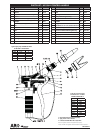
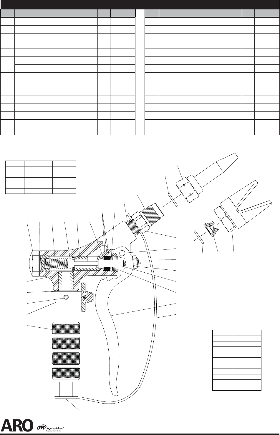
PARTS LIST / 651500-X CONTROL HANDLE
Item Description
(size)
(Qty) Part No. Item Description
(size)
(Qty) Part No.
1 Cap (1) 90395
9
2 Gasket (1) F21-23
9
3 Valve and Ball Seat Insert Assembly (1) 65732
4 Sleeve (1) 90332
5 Cap and Guard Assembly
(651500-1 only)
(1) 66504
6
Adapter
(651500 and 651500-1 only)
(1) 76751
(651500-2 only)
(1) 32854
7 Pin (1) 2487
8 Set Screw (1) 2484
9 Nut
(1/4” - 28)
(1) Y11-104-C
9
10 Piston Assembly (1) 65896
11 Retainer (1) 76886
12 Washer (1) F174-9
9
13 Packing (3) F26-35
14 Washer (1) F15-64
15 Lever (1) 2661
9
16 Ball (1) 90399
9
17 Spring (1) 76948
18 Body and Bushing Assembly (1) 65752
9
19 Gasket (1) F21-23
20 Handle (1) 4880
21 Trigger Guard (1) 90371
22 Set Screw
(#10 - 32 x 3/16”) (included with item 23)
(3) Y23-101
23 Knob Assembly (1) 66534
c
24
Extrusion Nozzle & Retaining Nut Ass’y (1) 66541-XX
c
25 Washer (1) 75815
c
26 Spray Tip (1) TC-XXXX
c
27 Washer (1) 91181
9
Items included in Service Kit 61240
16
16 3
14
14
17
171 2
12
12
4
25
25
24
24
27
27
26
26 5
8
9
10
10
11
11
15
15
21
21
3/8 - 18 N.P.T.F. - 1
3/8 - 18 N.P.T.F. - 1
18
18
19
19
22
22
23
23
20
20
6
7
13
13
11/16” - 16
11/16” - 16
c
Not included. Must be ordered separately.
d
Apply Loctite® 242® to threads.
e
Lubricate with Shell AW 32 Oil or equivalent.
y ARO® is a registered trademark of Ingersoll-Rand Company y
y Loctite® and 242® are registered trademarks of Henkel Loctite Corporation y
Tip No. Ori ce Diameter
66541-03 0.031”
66541-04 0.046”
66541-06 0.063”
66541-09 0.093”
66541-12 0.125”
66541-15 0.156”
66541-17 0.172”
66541-18 0.187”
66541-25 0.250”
66541-37 0.375”
Typical extrusion tips
available for models
651500 and 651500-2.
Typical spray tips available for mod-
els 651500-1 and 651500-3.
Tip No. Ori ce Diameter Pattern Width
TC-1850 0.018” 10”
TC-2140 0.021” 8.5”
TC-2150 0.021” 11.5”
TC-2640 0.026” 9”
TC-2650 0.026” 12”