


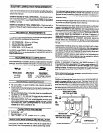
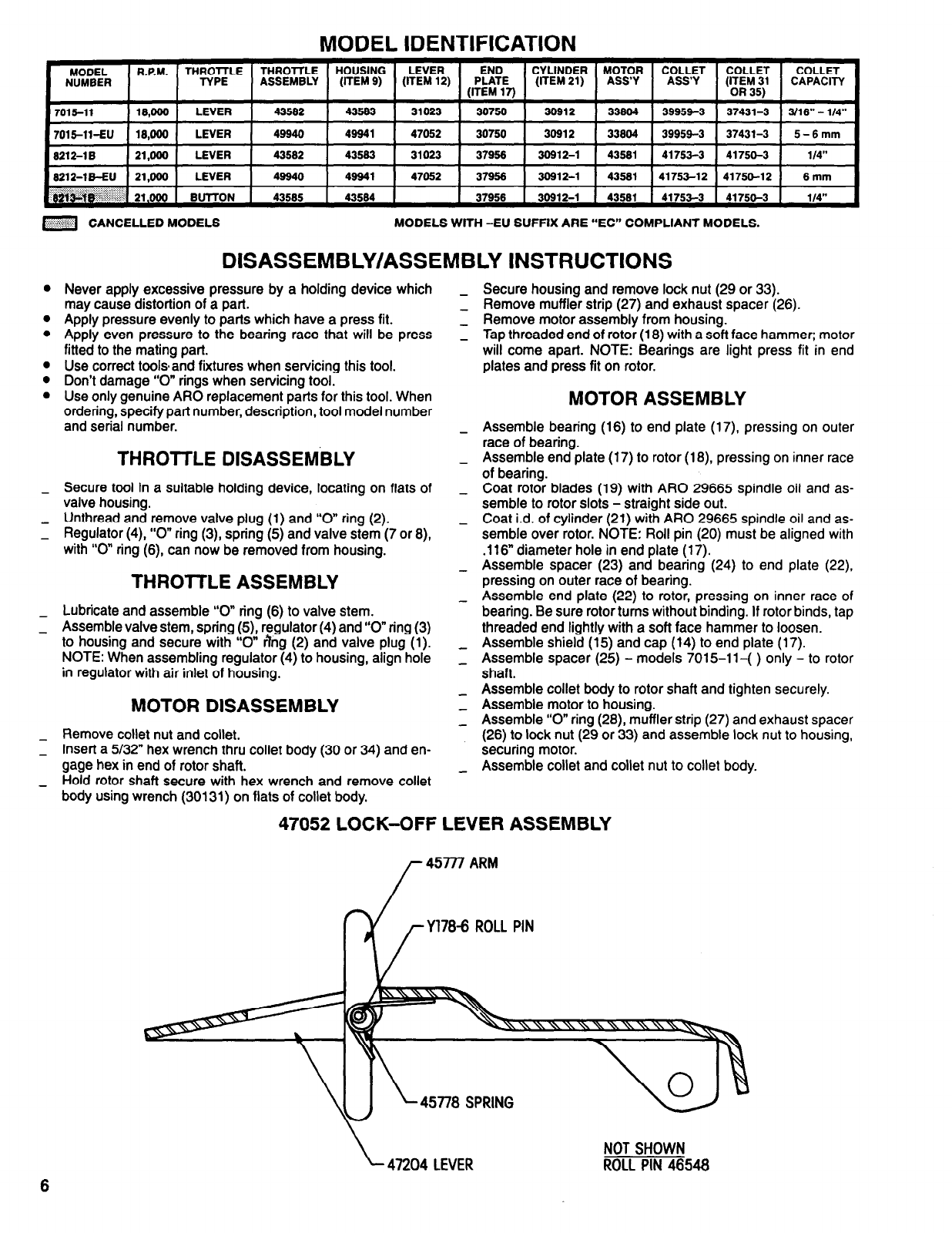
MODEL IDENTIFICATION
MODEL
NUMBER
7015-11
RPM
LEVER END CYLINDER MOTOR COLLET COLLET COLLET
THROTTLE THROTTLE HOUSING
ASSEMBLY
(ITEM 9)
(ITEM 12) PLATE
ASS’Y
ASS’Y
(ITEM 31
CAPACITY
(ITEM 17)
(ITEM 21)
or 35
18,000
LEVER 43582
43583 31023 30750 30612
33804 39954-3 37431-3 3/16” - 1/4”
7015-11-EU 18,000 LEVER 49940 46941 47052 30750 30912 33804 39959-3 37431-3 5-6mm
8212-1B 21,000 LEVER 43602 43583 31023 37968 30612-1 43581 41753-3 41750-3 1/4”
8212-1B-EU 21,000 LEVER 49640 49641 47052 37956 30612-1 43581 41753-12 41750-12 6mm
8213-1B 21,000 BUTTON 43685 43584 37956 30912-1 43581 41753-3 41750-3 1/4”
CANCELLED MODELS
MODELS WITH -EU SUFFIX ARE “EC” COMPLIANT MODELS.
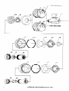
DISASSEMBLY/ASSEMBLY INSTRUCTIONS
l
l
0
l
l
0
-
-
-
-
Never apply excessive pressure by a holding device which
may cause distortion of a part.
Apply pressure evenly to parts which have a press fit.
Apply even pressure to the bearing race that will be press
fitted to the mating part.
Use correct tools and fixtures when servicing this tool.
Don’t damage “0” rings when servicing tool.
Use only genuine ARO replacement parts for this tool. When
ordering, specify part number, description, tool model number
and serial number.
THROTTLE DlSASSEMBLY
Secure tool in a suitable holding device, locating on flats of
valve housing.
Unthread and remove valve plug (1) and “0” ring (2).
Regulator (4), “0” ring (3), spring (5) and valve stem (7 or 8),
with “0” ring (6), can now be removed from housing.
THROTTLE ASSEMBLY
Lubricate and assemble “0” ring (6) to valve stem.
Assemble valve stem, spring (5) regulator (4) and “0” ring (3)
to housing and secure with “0” ring (2) and valve plug (1).
NOTE: When assembling regulator (4) to housing, align hole
in regulator with air inlet of housing.
MOTOR DISASSEMBLY
Remove collet nut and Collet.
Insert a 5/32” hex wrench thru collet body (30 or 34) and en-
gage hex in end of rotor shaft.
Hold rotor shaft secure with hex wrench and remove collet
body using wrench (30131) on flats of collet body.
Secure housing and remove lock nut (29 or 33).
Remove muffler strip (27) and exhaust spacer (26).
Remove motor assembly from housing.
Tap threaded end of rotor (18) with a soft face hammer; motor
will come apart. NOTE: Bearings are light press fit in end
plates and press fit on rotor.
MOTOR ASSEMBLY
Assemble bearing (16) to end plate (17) pressing on outer
race of bearing.
Assemble end plate (17) to rotor (18) pressing on inner race
of bearing.
Coat rotor blades (19) with ARO 29665 spindle oil and as-
semble to rotor slots - straight side out.
Coat i.d. of cylinder (21) with ARO 29665 spindle oil and as-
semble over rotor. NOTE: Roll pin (20) must be aligned with
.116” diameter hole in end plate (17).
Assemble spacer (23) and bearing (24) to end plate (22).
pressing on outer race of bearing.
Assemble end plate (22) to rotor, pressing on inner race of
bearing. Be sure rotor turns without binding. If rotor binds, tap
threaded end lightly with a soft face hammer to loosen.
Assemble shield (15) and cap (14) to end plate (17).
Assemble spacer (25) - models 7015-11-( ) only - to rotor
shaft.
Assemble collet body to rotor shaft and tighten securely.
Assemble motor to housing.
Assemble “0” ring (28) muffler strip (27) and exhaust spacer
(26) to lock nut (29 or 33) and assemble lock nut to housing,
securing motor.
Assemble collet and collet nut to collet body.
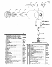
47052 LOCK-OFF LEVER ASSEMBLY
Y178-6 ROLL PIN
45778 SPRING
47204 LEVER
NOT SHOWN
ROLL PIN 48548