


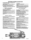

DISASSEMBLY/ASSEMBLY INSTRUCTIONS
Never apply excessive pressure by a holding device which
may cause distortion of a part.
Apply pressure evenly to parts which have a press fit.
Apply even pressure to the bearing race that will be press
fitted to the mating part.
Use correct tools and fixtures when servicing this tool.
Don’t damage “0” rings when servicing this tool.
Use only genuine ARO replacement parts for this tool. When
ordering, specify part number, description, tool model number
and serial number,
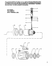
THROTTLE DISASSEMBLY
Remove roll pin (1), releasing lever (2).
To remove valve components, turn valve stem (11) to align
cross hole in valve stem with tool inlet.
Insert a 3/32” diameter dowel into cross hole in valve stem and
unthread button (5).
Remove retaining ring (6) and pull valve components from
housing.
Remove retaining ring (38) releasing valve (40) and “0” rings
from valve stem (11).
Remove retaining ring (13) and pad assembly (14) from hous-
ing (16).
Slide housing (16) out of oversleeve (4).
THROTTLE ASSEMBLY
Remove backing and wrap pad (18) around housing (16). with
adhesive side of pad toward housing. Assemble pad flush
with forward end of housing.
Remove backing and wrap pad (17) around housing (16), as-
sembling into groove, with adhesive side of pad toward hous-
ing.
Assemble one pad assembly (14) to housing (16). NOTE: As-
semble with metal washer toward housing.
Slide housing (16) into oversleeve (4). aligning holes forvalve.
Assemble pad (15) to housing, securing with pad assembly
(14) and retaining ring (13). NOTE: Assemble pad assembly
(14) with metal washer facing out.
Assemble spring (12) into housing, with large diameter of
spring going into housing first.
Grease and assemble “0” ring (10) to valve stem (11).
Grease and assemble “0” ring (39) to valve (40).
Assemble valve (40) to valve stem (11) securing with retain-
ing ring (38). NOTE: Assemble valve with large diameter to-
ward “0” ring (10).
Grease “0” rings (7 and 9) and assemble to grooves in bush-
ing (8).
Lubricate valve stem (11) with ARO 29665 spindle oil and as-
semble into bushing (8).
Assemble valve components into housing, securing with re-
taining ring (6). NOTE: Align hole in side of bushing (8) with air
inlet of housing.
Insert a 3/32” diameter dowel into cross hole in valve stem (11)
and thread button (5) onto valve stem.
Assemble pad (3) to underside of lever (2) centering pad over
button (5).
Assemble lever (2) to oversleeve (4) securing with roll pin (1).
NOTE: At assembly, the orientation of housing (16) and over-
sleeve (4) is to be centered at the area of valve stem (11). Ad-
justments can be made by placing a wrench on wrench flats at
inlet of the tool and turning housing in oversleeve.
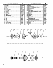
MOTOR DISASSEMBLY
Remove collet nut (36) and collet (37).
Insert a 5/32” hex wrench thru collet body and engage hex in
end of rotor shaft.
Hold rotor shaft secure with hex wrench and remove collet
body (35) using wrench on flats of collet body.
Clamp tool in a smooth face vise, clamping on flats of air inlet.
Using a spanner wrench, remove lock nut (33).
Remove felt strip (31) and exhaust spacer (30).
Remove motor assembly from housing.
Tap threaded end of rotor (23) with a soft face hammer; motor
will come apart. NOTE: Bearings are light press fit on rotor.
Bearing (29) is press fit in end plate.
Remove end plate (22) and bearing (21) from rotor.
MOTOR ASSEMBLY
Assemble bearing (21) into end plate (22), pressing on outer
race of bearing.
Assemble end plate (22) to rotor, pressing on inner race of
bearing.
Coat four rotor blades (24) with ARO 29665 spindle oil and as-
semble to rotor slots - straight side out.
Coat i.d. of cylinder (26) with ARO 29665 spindle oil and as-
semble over rotor. NOTE: Roll pin (25) must be aligned with
.116” diameter hole in end plate (22).
Lubricate bearing (29) with ARO 33153 grease,
Assemble spacer (28) and bearing (29) into end plate (27)
pressing on outer race of bearing. NOTE: Assemble bearing
with shielded side facing out.
Assemble end plate (27) to rotor, pressing on inner race of
bearing. Be sure rotor turns without binding.
Assemble shield (20) and cap (19) to end plate (21).
Assemble spacer (34) and collet body (35) to rotor and tighten
collet body securely.
Assemble motor assembly into housing (16).
Grease and assemble “0” ring (32) to lock nut (33).
Assemble felt strip (31) and exhaust spacer (30) to lock nut
(33) and assemble lock nut to housing, securing motor.
Assemble collet (37) and collet nut (36) to collet body (35).
PN 49999-084