


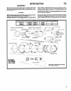
MOTOR SECTION
M10
43
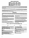
DISASSEMBLY
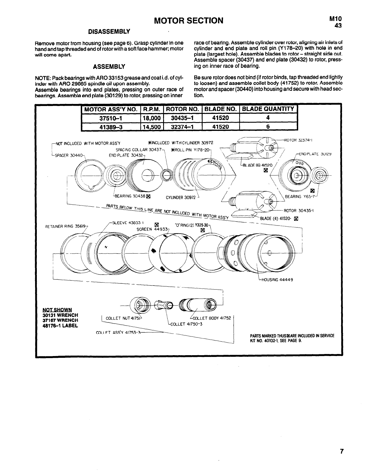
Remove motor from housing (see page 6). Grasp cylinder in one
race of bearing. Assemble cylinder over rotor, aligning air inlets of
hand and tap threaded end of rotor with a soft face hammer; motor
cylinder and end plate and roll pin (Y17B-20) with hole in end
will come apart.
plate (largest hole). Assemble blades to rotor - straight side out.
Assemble spacer (30437) and end plate (30432) to rotor, press-
ASSEMBLY
ing on inner race of bearing.
NOTE: Pack bearings with ARO 33153 grease and coat i.d. of cyl-
Be sure rotor does not bind (if rotor binds, tap threaded end lightly
inder with ARO 29665 spindle oil upon assembly.
to loosen) and assemble collet body (41752) to rotor. Assemble
Assemble bearings into end plates, pressing on outer race of
motor and spacer (30440) into housing and secure with head sec-
bearings. Assemble end plate (30129) to rotor, pressing on inner
tion.
MOTOR ASS’Y NO. R.P.M. ROTOR NO. BLADE NO. BLADE QUANTITY
37510-1
18,000
30435-l
41520
4
41389-3
14,500
32374-l
41520
6
NOT INCLUDED WITH MOTOR ASS’Y
#INCLUDED WITH CYLINDER 30972
PARTS MARKED THUS ARE INCLUDED IN SERVICE
KIT NO. 40102-l. SEE PAGE 9.