


GRINDING WHEEL MOUNTING INSTRUCTIONS
M10
43
Disconnect air supply from grinder or shut off air supply and exhaust (drain) air
line of compressed air before mounting or removing any abrasive wheel or wire
brush, or otherwise performing maintenance or service to the tool.
Check abrasive wheels prior to mounting for chips or cracks. Cracked or chipped
wheels shall not be used.
Care must be taken that a grinding wheel, or wire brush, of the correct speed rat-
ing is used. Rated wheel capacities for Aro grinders are maximum only. Regard-
less of the rated capacity and speed of any Aro grinder, abrasive wheels or wire
brushes shall never be operated at a speed greater than that recommended by
the wheel (or brush) manufacturer.
Check grinder speed before mounting grinding wheel (or other type accessory)
with a reliable tachometer to make sure that the actual speed of the grinder does
not exceed its rated free speed.
Check operating speed of grinding wheel or wire brush to be used with the grind-
er. The maximum operating speed marked on the grinding wheel, blotters or
packaging, shall equal or exceed the rated free speed of the grinder. Also, the
type and size of the grinding wheel or wire brush shall be compatible with the
grinder size and type.
Dressing Abrasive Wheels. Upon mounting a grinding wheel, the tool should be
operated at gradually increasing speed and checked for good balance of the
wheel. If unbalance is observed, the wheel shall be dressed. If dressing fails to
establish acceptable balance, the wheel shall not be used.
MOUNTING INSTRUCTIONS FOR MOUNTED WHEELS
FOR USE WITH COLLET ASSEMBLIES.
The collet shall be checked to assure it to be in good condition and properly af-
fixed to the grinder spindle.
The mandrel shall be inserted to the full depth of the gripping jaws of the collet. At
least 1/2 the mandrel length shall be inserted into the Collet.
The maximum safe operating speed for mounted wheels shall be determined by
the following: 1.) Shape and size of the mountedwheel, 2.) Size of mandrel and
3.) Overhang of mandrel. In no case shall the maximum safe operating speed rec-
ommended by the wheel manufacturer be exceeded.
WARNING: Work pressure, if excessive, can be the cause of trouble and a
source of danger, thru bending or fracture of the mandrel. Pressure be-
tween the wheel and the work should never be so heavy that springing of
the mandrel will result.
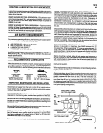
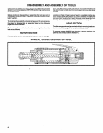
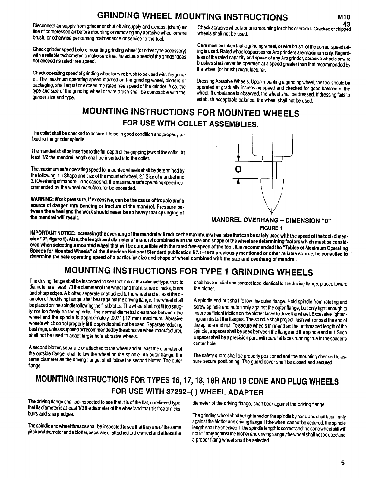
MANDREL OVERHANG - DIMENSION “0”
FIGURE 1
IMPORTANT NOTICE: lncreaslng the overhang of the mandrel will reduce the maximum wheel size that can be safely used with the speed of the tool (dlmen-
slon “0”, figure 1). Also, the length and diameter of mandrel combined with the size and shape of the wheel are determining factors which must be consid-
ered when selecting a mounted wheel that will be compatible with the rated free speed of the tool. It is recommended the “Tables of Maximum Operating
Speeds for Mounted Wheels” of the American National Standard publication 87.1-1979 previously mentioned or other reliable source, be consulted to
determine the safe operating speed of a particular size and shape of wheel combined with the size and overhang of mandrel.
MOUNTING INSTRUCTIONS FOR TYPE 1 GRINDING WHEELS
The driving flange shall be inspected to see that it is of the relieved type, that its
diameter is at least 1/3 the diameter of the wheel and that it is free of nicks, burrs
and sharp edges. A blotter, separate or attached to the wheel and at least the di-
a meter of the driving flange, shall bear against the driving flange. The wheel shall
be placed on the spindle following the first blotter. The wheel shall not fit too snug-
ly nor too freely on the spindle. The normal diametral clearance between the
wheel
and
the spindle is approximately ,007” (.17 mm) maximum. Abrasive
wheels which do not properly fit the spindle shall not be used. Separate reducing
bushings, unless supplied or recommended by theabrasive wheel manufacturer,
shall not be used to adapt larger hole abrasive wheels.
A second blotter, separate or attached to the wheel and at least the diameter of
the outside flange, shall follow the wheel on the spindle. An outer flange, the
same diameter as the driving flange, shall follow the second blotter. The outer
flange
shall have a relief and contact face identical to the driving flange, placed toward
the blotter.
A spindle end nut shall follow the outer flange. Hold spindle from rotating and
screw spindle end nuts firmly against the outer flange, but only tight enough to
insure sufficient friction on the blotter faces to drive the wheel. Excessive tighten-
ing can distort the flanges. The spindle shall project flush with or past the end of
the spindle end nut. To secure wheels thinnerthan the unthreaded length of the
spindle,a spacer shall be used between the flange and the spindle end nut. Such
a spacer shall be a precision part, with parallel faces running true to the spacer’s
center hole.
The safety guard shall be properly positioned and the mounting checked to as-
sure secure positioning. The guard cover shall be closed and secured.
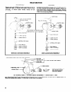
MOUNTING INSTRUCTIONS FOR TYPES 16, 17, 18, 18R AND 19 CONE AND PLUG WHEELS
FOR USE WITH 37292-( ) WHEEL ADAPTER
The driving flange shall be inspected to see that it is of the flat, unrelieved type,
that its diameter is at least 1/3 the diameter of the wheel and that
it is free of nicks,
diameter of the driving flange, shall bear against the driving flange.
burrs and sharp edges.
The grinding wheel shall be tightened on the spindle by hand and shall bearfirmly
The spindle and wheel threads shall be inspected to see that they are of the same
against the blotter and driving flange. If the wheel cannot be secured, the spindle
pitch and diameter and a blotter, separate or attached to the wheel and at least the
length shall be checked. If the spindle length is correct and the cone wheel still will
not fit firmly against the blotter and driving flange, the wheel shall not be used and
a proper fitting wheel shall be selected.
5